background image

Power supply 


8.2 SIDOOR NT40 


ATE500E 

114


System Manual, 09/2017, A5E33917696-AD 

Procedure 


Note 
Risk of injury due to moving mechanical parts 
The control system will become ready for operation after the supply line has been 

connected. If a control signal is present, the door will move in the set direction. 
Always connect the supply lines last of all! 


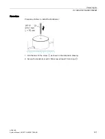
Carry out the following steps in the given order: 
1.


Connect the controller to output line X2. Observe the polarity printed on the device. 

2.


Connect the supply line X1 to the supply network. 

3.


When the supply is switched on, the device is ready for operation. 
The green LED lights up. 

See Section Connection and commissioning (Page 137). 

Summary of Contents for SIDOOR ATE500E

Page 1: ......

Page 2: ...______________ ___________________ ___________________ ___________________ Automatic Door Controls SIDOOR ATE500E System Manual 09 2017 A5E33917696 AD Introduction 1 General safety instructions 2 Product family 3 Application 4 Product combinations 5 Controller 6 Motor 7 Power supply 8 Connection and commissioning 9 Additional units 10 Appendix A ...

Page 3: ... personnel qualified for the specific task in accordance with the relevant documentation in particular its warning notices and safety instructions Qualified personnel are those who based on their training and experience are capable of identifying risks and avoiding potential hazards when working with these products systems Proper use of Siemens products Note the following WARNING Siemens products ...

Page 4: ... CLOSE command given via digital inputs 27 6 2 6 DOOR OPEN command given via digital inputs 28 6 2 7 Restart after power failure 28 6 2 8 Overload protection 29 6 2 9 Vandalism protection continuous door monitoring 29 6 2 10 Obstruction detection 30 6 2 10 1 Obstruction detection CLOSE 30 6 2 10 2 Obstruction detection OPEN 30 6 2 10 3 Obstruction detection process 31 6 2 11 Belt break monitoring ...

Page 5: ...ule 71 6 6 6 Power supply 77 6 7 Motor plug 77 6 8 Parameters 78 6 8 1 Driving curve 78 6 8 2 Forces 79 6 9 Diagnostics 82 6 9 1 Operating state display 82 6 10 Technical specifications 86 7 Motor 90 7 1 Description 90 7 2 Installation 91 7 3 Span tension 97 7 4 Connecting terminals 98 7 5 Technical specifications 99 8 Power supply 105 8 1 Direct voltage supply provided by customer 105 8 1 1 Requi...

Page 6: ...cifications 134 9 Connection and commissioning 137 10 Additional units 143 10 1 SIDOOR SERVICE TOOL 143 10 1 1 Description 143 10 1 2 Connection 144 10 1 3 Operation 145 10 1 4 Technical specifications 147 A Appendix 148 A 1 Profiles and adjustment ranges 148 A 1 1 Profile name 148 A 1 2 MED280 profile 149 A 1 3 MED280 adjustment ranges 150 A 2 Configuration record 151 A 3 Service support 153 Inde...

Page 7: ...System Manual Target group The System Manual is intended for fitters commissioning engineers operators service personnel and elevator configuration engineers Firmware versions This System Manual applies to controllers as from the following firmware version Controller From firmware version SIDOOR ATE500E 1 1 Figures The illustrations in this System Manual show SIDOOR ATE500E controller version 1 1 ...

Page 8: ...51 Have this record to hand when you call the Hotline History Version Change 02 2015 First edition 05 2016 Revised and expanded edition 09 2017 Revised and expanded edition Recycling and disposal For ecologically sustainable recycling and disposal of your old device contact a certificated disposal service for electronic scrap or dispose of the device in accordance with the regulations in your coun...

Page 9: ...aining Working on the door drive WARNING Risk of injury due to dangerous electrical voltages and moving mechanical parts Disconnect the door drive by pulling the power plug from the power supply or by clearing SIDOOR TRANSFORMER UL before you start work on the door drive WARNING Risk of injury due to moving mechanical parts If power operated guards are used ensure that they have been tested prior ...

Page 10: ...on In the event of a controller failure measures must be taken for emergency operation according to the application Modifications to the door drive CAUTION Loss of liability for defects and material damage Changes to the door drive lead to the loss of liability for defects and compensation rights and the correct function of the door drive is no longer guaranteed Note the following rules Do not mak...

Page 11: ...inst cyber threats it is necessary to implement and continuously maintain a holistic state of the art industrial security concept Siemens products and solutions constitute one element of such a concept Customers are responsible for preventing unauthorized access to their plants systems machines and networks Such systems machines and components should only be connected to an enterprise network or t...

Page 12: ...ates namely for the open and closed positions of the door The door is always controlled between these two positions in accordance with the guidelines In a defined learn run initiated at the touch of a button one button commissioning the door system automatically determines the values for the door width the dynamic door weight the inhibitive force in the opening direction the inhibitive force in th...

Page 13: ...Product family 3 1 Overview ATE500E System Manual 09 2017 A5E33917696 AD 13 Overview of the product family Figure 3 1 System setup EC technology The ATE500E controller supports three phase EC motors ...

Page 14: ...ce The controllers are designed for different areas of application The following table provides an overview of the available controllers Versions Product Article No Description SIDOOR ATE500E RELAY 6FB1211 5AT10 7AT2 Controller for elevator doors horizontal Dynamic door weights of up to 280 kg can be driven with the SIDOOR MED280 motor Relay module SIDOOR ATE500E CAN 6FB1211 1AT10 7AT3 Controller ...

Page 15: ...trolled The set force and speed limits are not exceeded The force is transmitted by a toothed belt The toothed belt passes over a deflector pulley and can be fitted with 2 clutch holders This enables it to drive both single sided and centrally opening doors Product Article No Description SIDOOR MED280 6FB1203 0AT12 7DA0 EC motor max door weight of 275 kg Cable length 1 5 m ...

Page 16: ...hing both ends of the toothed belt and for con necting the respective door panel to the toothed belt SIDOOR deflector unit 6FB1104 0AT07 0AS0 Deflector unit with deflector pulley For deflecting the SIDOOR toothed belt in the same height and depth aligned with motor drive pinion SIDOOR mounting bracket 6FB1104 0AT05 0AS4 Mounting bracket large with tensioning device For mounting the SIDOOR deflecto...

Page 17: ... connect the controllers to the respective application specific power supply Device selection Product Article No Description SIDOOR NT40 6FB1112 0AT20 3PS0 Power supply for controllers without an integrated power supply unit SIDOOR TRANSFORMER 6FB1112 0AT20 2TR0 SIDOOR TRANSFORMER UL 6FB1112 0AT21 2TR0 Direct voltage supply provided by customer see Section 8 1 Page 105 ...

Page 18: ...2 SIDOOR SERVICE TOOL D SUB connecting cable 9 pin socket socket D SUB connecting cable 9 pin plug socket USB connecting cable USB adapter Installation CD Figure 3 3 SIDOOR SOFTWARE KIT Additional units meet a range of customer requirements in order to ensure the universal implementation and maintenance of the system ...

Page 19: ... socket length 2 m SIDOOR SOFTWARE KIT 6FB1105 0AT01 6SW0 The optional SIDOOR Software Kit facilitates user friendly operation and detailed diagnostics via a PC The package includes the following components Installation CD Software Kit SIDOOR User Software Siemens HCS12 Firmware Loader SIDOOR USB to UART Bridge driver SIDOOR Manager License provisions SIDOOR Software Kit Operating Instructions 1x ...

Page 20: ...al 09 2017 A5E33917696 AD Application 4 The comfort SIDOOR ATE500E elevator door drive is an intelligent door drive that can open and close cabin and shaft doors at adjustable speeds accelerations and with adjustable forces ...

Page 21: ...roducts that can be combined with the SIDOOR ATE500E controller Table 5 1 Overview of product combinations SIDOOR ATE500E Motor SIDOOR MED280 Power supply SIDOOR NT40 SIDOOR TRANSFORMER SIDOOR TRANSFORMER UL DC supply according to Section Page 105 Additional units SIDOOR SOFTWARE KIT SIDOOR SERVICE TOOL ...

Page 22: ...ATE500E 22 System Manual 09 2017 A5E33917696 AD Controller 6 6 1 Description Overview Connecting terminals Relay module CAN module Service buttons Minimal editor ...

Page 23: ...puts Page 27 DOOR OPEN command given via digital inputs Page 28 Restart after power failure Page 28 Overload protection Page 29 Vandalism protection continuous door monitoring Page 29 Obstruction detection Page 30 Belt break monitoring Page 31 Oscillation protection Page 32 Automatic energy limitation Page 33 External closing force Page 37 Emergency release Page 38 Learn run Page 38 Service button...

Page 24: ...ssignment The light barrier signal can be connected to the LIGHT BARRIER DCPS input of terminal X6 See also Section Digital input signals Page 62 The connected signal must be activated via the SIDOOR SERVICE TOOL Main menu General setup Special parameters Input 1 Note The light barrier and DCPS Door Closed Position Sensor Page 25 functions cannot be implemented simultaneously Signals Signal Descri...

Page 25: ... switched off if the elevator is not going to be used for a lengthy period for example during the night If the contact remains closed although the door has left its CLOSED position the controller switches to initial operation after 10 cm and continues the movement at initial speed The door does not resume moving at normal speed until after it has traveled to both end positions with the correct DCP...

Page 26: ...ve in conjunction with the CLOSE input signal Signals Signal Description 1 voltage applied The nudge command is present if the DOOR CLOSE command is activated at the same time The reversing unit is deactivated 0 voltage not applied The nudge command is not present 6 2 4 Stopping Description of function If the drive command is withdrawn while the door is moving and if no further drive command is pr...

Page 27: ...LOSED position the door is pressed into the CLOSED position for 2 s with the closing press on torque Continuous torque CLOSE parameter Then if the DOOR CLOSE command is present the door is held closed at a torque that can be adjusted by the parameter Continuous torque CLOSE Note If the commands DOOR CLOSE and DOOR OPEN are present simultaneously the door always moves in the OPEN direction Connecti...

Page 28: ... Connection The DOOR OPEN function is connected to the OPEN input of terminal X6 See also Section Digital input signals Page 62 Signals Signal Description 1 voltage applied The DOOR OPEN command is present 0 voltage not applied The DOOR OPEN command is not present 6 2 7 Restart after power failure Description of function After a power failure the controller has to redetermine the end positions of ...

Page 29: ...e Motor Controller 95 100 91 95 Reduction of the acceleration and braking ramps to a minimum of 300 mm s 83 100 80 95 Reduction of the maximum speed to a minimum of 150 mm s 95 100 91 95 Increase of the hold open time to between 2 and 10 seconds 83 100 80 95 Increase of the idle time în the event of oscillation in the end position between 10 and 30 seconds 100 95 When stopped the motor is deenergi...

Page 30: ... obstruction detection serves to detect the end position 6 2 10 2 Obstruction detection OPEN Description of function The door stops if it is obstructed in the OPEN direction when the DOOR OPEN command is present After approximately 2 s the door automatically tries to reach the OPEN position again This action is repeated a maximum of 3 times The motor is then deenergized If the DOOR OPEN command is...

Page 31: ...pper force limit a force obstruction is detected in the current drive direction Stop obstruction detection If the current speed is less than 10 mm s for longer than 0 3 s in the closing direction or 0 5 s in the opening direction a stop obstruction is detected in the current drive direction Note Behavior according to the door mode Obstruction detection is only active in Normal mode and in the stat...

Page 32: ...ation of the idle time is between 10 and 30 s and depends on the overload state of the controller and or motor See also Section Overload protection Page 29 End position closed If the system is pressed out of the end position with the drive order close present the system detects that the closed position has been left and attempts to return to the end stop with the set static cutter force After reac...

Page 33: ... parts Irrespective of the maximum closing speed determined automatically during the learn run after a learn run the kinetic energy of the door in the closing direction must be checked by the commissioning engineer According to EN 81 the kinetic energy of the door in the closing direction must not exceed 10 joules while the reversing device is enabled Without enabled reversing device the kinetic e...

Page 34: ...ve 75 joules in opening direction The speed limit curve is the characteristic curve for determining the maximum permissible door speed opening speed vmax as a function of the effectively moved door mass m Effectively moved door weight m 275 kg vmax 0 73 m s Figure 6 1 Speed limit curve 75 joules ...

Page 35: ...e 10 joules in closing direction According to EN 81 the maximum kinetic energy of the door in the closing direction must not exceed 10 joules WKIN 1 2 m v 10 J Example from the following speed limit curve Effectively moved door weight m 275 kg vmax 0 27 m s Figure 6 2 Speed limit curve 10 joules ...

Page 36: ...the maximum kinetic energy must not exceed 4 joules while the reversing device is disabled WKIN 1 2 m v 4 J Example from the following speed limit curve Effectively moved door weight m 275 kg vmax 0 17 m s Figure 6 3 Speed limit curve 4 joules Adjustment ranges You will find the adjustment ranges in Section Profiles and adjustment ranges Page 148 ...

Page 37: ...179 283 447 632 775 894 300 163 258 408 577 707 816 6 2 14 External closing force Description of function Closing mechanisms in the form of a counterweight or a spring are permissible for a particular system You will find the permissible counterweights in Section Technical specifications Page 86 WARNING Risk of injury due to moving mechanical parts Ensure that if there is an additional external cl...

Page 38: ...he force required to open the door is less than 300 N in accordance with the requirement of EN 81 Check additional final application specific requirements 6 2 16 Learn run Description of function A learn run serves to determine and store the system characteristics of the door WARNING Risk of injury during commissioning The door movements cannot always be externally controlled while the controller ...

Page 39: ...r is safely cordoned off Starting a learn run via the learn run button You can start a learn run by pressing the learn run button S401 Proceed as described in Section Service buttons Page 43 Requirements Types of learn run via learn run button Two types of learn run can be made if the learn run button is pressed as follows When the supply voltage is applied If the learn run button S401 is pressed ...

Page 40: ...rror during the learn run The 7 segment display H401 displays the status code P_ A canceled learn run can be restarted by pressing the learn run button S401 again After a learn run has been canceled switching to normal operation can only be performed by restarting the controller disconnecting the power supply from the network Learnt door parameters The learn run determines the following values Mot...

Page 41: ...e safe force output of the SIDOOR system ensures that the torque output by the motor does not increase in case of an error Unintentional increases in the torque are recognized and result in a defined error response 6 3 2 Safe speed observance energy limiting The speeds configured by the user must always be observed for safety reasons The safe speed observance of the SIDOOR system ensures that the ...

Page 42: ...evices SIDOOR SERVICE TOOL SIDOOR SOFTWARE KIT Note After the optimal parameter settings have been determined note them in the configuration record see Appendix Configuration record Page 151 Have this record to hand when you call the Hotline Note Parameter changes Parameters should always be adjusted during normal operation with the door in the CLOSED position because the controller then accepts t...

Page 43: ...g commissioning Increased forces speeds and energies arise in the closing and opening directions during the learn run Therefore ensure that the door is secured with physical barriers prior to a learn run and during commissioning Note Two types of learn run can be carried out See Section Learn run Page 38 Note Cancelation of learn run Pressing the learn run button S401 or the OPEN S402 or CLOSE S40...

Page 44: ...osition This means that the door width and weight are re adapted and saved The standard parameters for energy limitation speed limitation and all other driving curve parameters are also loaded 8 Learn run completed The door is in the CLOSED position Learn run during operation Table 6 4 Starting a learn run during operation Procedure H401 display 1 Push the door into the CLOSED position or move it ...

Page 45: ... must therefore ensure that the door is safely cordoned off Cancelation of a learn run If the status code H is shown on the 7 Segment display H401 an active learn run can be canceled by pressing the OPEN S402 or CLOSE S403 service button A learn run can also be canceled by pressing the learn run button S401 again Note After a cancelled learn run changing over to normal operation is only possible t...

Page 46: ...or The Minimal editor is a utility for changing parameters at a controller when the SIDOOR SERVICE TOOL or the SIDOOR USER SOFTWARE is not available In this case the learn run button S401 and the two service buttons S402 S403 are assigned second functions The LED display H401 is used to visualize messages You can use the minimal editor to perform the following settings Select a fixed profile Set t...

Page 47: ...ranges Page 148 Activating the minimal editor 1 Disconnect the controller from the power supply by unplugging the power plug The line voltage can alternatively be connected and disconnected with the X3 connector directly on the controller 2 Press and hold down the S402 and S403 buttons simultaneously and reestablish the line voltage by plugging the power plug back in Continue to hold down both but...

Page 48: ... or S403 upwards 2 Confirm the profile you have set by pressing and holding down the learn run button S401 until the dot lights up on the LED display 2 seconds The dot on the LED display indicates that the settings have been stored successfully Note If the learn run button S401 is pressed only briefly the minimal editor switches to the closing forces setting menu The newly set profile is not saved...

Page 49: ...t changes the closing force as it is subtracted from the maximum value of 150 N The setting 6 thus reduces the closing force to 90 N 150 N 60 N 90 N 4 Confirm the closing force you have selected by pressing and holding down the learn run button S401 until the dot lights up on the LED display 2 seconds The dot on the LED display indicates that the settings have been stored successfully Note If the ...

Page 50: ...so be assigned to the SIDOOR controller via the following additional units SIDOOR USER SOFTWARE The SIDOOR User Software is part of the SIDOOR SOFTWARE KIT You can find a detailed description of the SIDOOR SOFTWARE KIT in the SIDOOR SOFTWARE KIT Operating Instructions http support automation siemens com WW view en 92711247 SIDOOR SERVICE TOOL You can find a detailed description of the SIDOOR SERVI...

Page 51: ...p speed OPEN slow end speed open Cutter speed OPEN slow start speed open Initial speed OPEN slow speed open initial Maximum speed CLOSE maximum speed close Creep speed CLOSE slow start speed close Cutter speed CLOSE slow end speed close Initial speed CLOSE slow speed close initial Nudge speed CLOSE nudging speed Acceleration ramp OPEN acceler ramp open Braking ramp OPEN Braking ramp OPEN Reversing...

Page 52: ...Controller 6 4 Operation and parameter assignment ATE500E 52 System Manual 09 2017 A5E33917696 AD 6 4 5 Navigation structure ...

Page 53: ...Controller 6 4 Operation and parameter assignment ATE500E System Manual 09 2017 A5E33917696 AD 53 ...

Page 54: ...Controller 6 4 Operation and parameter assignment ATE500E 54 System Manual 09 2017 A5E33917696 AD ...

Page 55: ...Controller 6 4 Operation and parameter assignment ATE500E System Manual 09 2017 A5E33917696 AD 55 1 Displayed door states open closed open close test stopped ...

Page 56: ...Controller 6 4 Operation and parameter assignment ATE500E 56 System Manual 09 2017 A5E33917696 AD ...

Page 57: ...Controller 6 4 Operation and parameter assignment ATE500E System Manual 09 2017 A5E33917696 AD 57 ...

Page 58: ...Controller 6 4 Operation and parameter assignment ATE500E 58 System Manual 09 2017 A5E33917696 AD ...

Page 59: ...5 m Maximum distance from the motor on account of the cable length SIDOOR MED280 1 5 m WARNING Risk of injury as a result of incorrect installation The controller must only be used indoors Final application specific requirements must be observed In an NFPA industrial environment The controller fulfills the requirements for insulation against fire only when the cover is closed and if it is installe...

Page 60: ...s 6 6 Connecting terminals and interfaces 6 6 1 Wiring instructions NOTICE Material damage Only use cables with a temperature range 85 C Table 6 5 Properties of slots and interfaces Slot Name Maxi mum cable length Type X3 Power supply 30 m Not shielded supply X4 24 V voltage output 30 m Not shielded supply see section Voltage output Page 65 X6 Digital inputs 30 m Not shielded asymmetric data cable...

Page 61: ...le 6 6 Properties of slots and interfaces Slot X3 X4 X6 Connector WAGO 721 103 026 045 PHOENIX 1792757 PHOENIX 1792799 SZS 0 6x3 5 SZS 0 6x3 5 SZS 0 6x3 5 1x1 5 2 5mm2 1x0 2 2 5mm2 1x0 2 2 5mm2 1x1 5 2 5mm2 1x0 2 2 5mm2 1x0 2 2 5mm2 AWG 15 12 30 12 30 12 Nm 0 5 0 6 0 5 0 6 8 9 mm 7 mm 7 mm L 30 m L 30 m ...

Page 62: ... 28 NOTICE Settings required if the LIGHT BARRIER DCPS input is not used The following settings must be made if the LIGHT BARRIER DCPS input is not used for the light barrier or the DCPS X6 must be wired to X4 as shown in the following connection diagram and there must be a jumper on the light barrier signal The LIGHT BARRIER DCPS input must be configured as inactive Note The LIGHT BARRIER DCPS in...

Page 63: ...gnals NOTICE Settings required if the LIGHT BARRIER DCPS input is not used A jumper between X6 und X4 is required if the LIGHT BARRIER DCPS input is not used for the light barrier or the DCPS and the LIGHT BARRIER DCPS input is not configured as inactive a Connection to an internal 24 V control voltage b Connection to an external control voltage ...

Page 64: ...9 2017 A5E33917696 AD c Connection to an internal 24 V control voltage LIGHT BARRIER DCPS input and an external control voltage NUDGING CLOSE and OPEN inputs d Connection to an external 24 V control voltage LIGHT BARRIER DCPS input isolated from the NUDGING CLOSE and OPEN inputs ...

Page 65: ...s a control voltage for supplying the control inputs Use shielded cables shield to be applied by the customer if the output in the elevator system is used as a supply output in accordance with EN 12015 as described in Section 6 3 and the cable is longer than 2 m Slot X4 Function DC OUTPUT 24 V 10 max 400 mA See also Digital input signals Page 62 ...

Page 66: ...ule Overview X11 X13 X12 Protective cover Fixing screw for the protective cover Figure 6 5 Relay module Slot Name Maximum cable length Type X11 Digital output 30 m Not shielded asymmetric data cable X12 Digital output 30 m Not shielded asymmetric data cable X13 Digital output 30 m Not shielded asymmetric data cable ...

Page 67: ... 8 Properties of slots and interfaces Slot X11 X12 X13 Connector PHOENIX 1757022 PHOENIX 1757022 PHOENIX 1757022 SZS 0 6x3 5 SZS 0 6x3 5 SZS 0 6x3 5 1x0 2 2 5mm2 1x0 2 2 5mm2 1x0 2 2 5mm2 1x0 2 2 5mm2 1x0 2 2 5mm2 1x0 2 2 5mm2 AWG 30 12 30 12 30 12 Nm 0 5 0 6 0 5 0 6 0 5 0 6 7 mm 7 mm 7 mm L 30m L 30m L 30m ...

Page 68: ...interruption of the light barrier or an opening command Pin 1 is then connected to Pin 3 until the OPEN position is reached X13 The door has reached the OPEN position The relay switches on when the distance of the door from the OPEN position falls below 1 cm Pin 1 and Pin 3 are then connected The relay drops out immediately as soon as the distance exceeds 1 cm again and Pin 3 is once again connect...

Page 69: ...V and 230 V must not be connected to the relay module Cable ties strain relief in housing Cable ties security against being pulled out within the protective cover Minimum length of the cable jacket within the protective cover 5 mm Minimum length of the single insulation on the single cores 5 mm Insertion direction for the protective cover Fixing screw for the protective cover 1 Unscrew the fixing ...

Page 70: ...urpose tie each of them tightly round the cable Ensure that the cable tie is tied so that at least 5 mm of the outer cable jacket lies inside the protective cover 6 Provide additional strain relief by attaching more cable ties to the fixing points provided in the housing 7 Slide the protective cover in the insertion direction back into its correct position 8 Screw the fixing screw holding the prot...

Page 71: ...le Overview X11 H2 X16 H3 S1 X15 Protective cover Fixing screw for the protective cover H1 Figure 6 6 CAN module Slot Name Maximum cable length Type X11 Digital outputs 30 m Not shielded asymmetric data cable X15 CAN interface 30 m Shielded symmetric data cable X16 CAN interface 30 m Shielded symmetric data cable ...

Page 72: ...NIX 1803594 RJ45 Cat 5 PHOENIX 1803581 SZS 0 4x2 5 SZS 0 4x2 5 1x0 14 1 5mm2 1x0 14 1 5mm2 1x0 14 1 5mm2 1x0 14 1 5mm2 AWG 30 14 30 14 Nm 0 22 0 25 0 22 0 25 7 mm 7 mm L 30m L 30m L 30m Task The CAN module enables the SIDOOR ATE500E door controller to be connected to a CAN bus A maximum of 32 nodes can be connected to the CAN bus ...

Page 73: ...ired CANopen node ID 7 Baud rate Automatic Door number 1 When the baud rate is set to automatic the CAN module automatically determines the baud rate on the CAN bus To do this the CAN module must have received some valid CAN telegrams The LED H3 flashes at 5 Hz quick flashing while the baud rate is being automatically determined LED signals All LED signals are listed in the following table LED sig...

Page 74: ...ollowing protective measures before removing the protective cover Disconnect the controller from all live cables By grounding ensure that the user fitter the controller and other conductors have the same voltage potential Observe the general ESD guidelines Wiring Table 6 10 Connector X15 Pin assignment Pin Signal 1 CAN_H 2 CAN_L 3 GND 4 5 6 Shield 7 GND 8 Table 6 11 Connector X16 Pin assignment Pi...

Page 75: ...o two relays on the CAN module They can switch a maximum of 30 V and 0 5 A The pin assignments are Table 6 12 Connector X11 Pin assignment Pin Assignment Description 1 2 NO contact CLOSED position reached The relay switches on when the controller has detected the CLOSED position and the incremental sensor ceases to output pulses LED H1 is on 3 4 NO contact OPEN position reached The relay switches ...

Page 76: ...tors X11 X15 and X16 4 Ensure that inside the cover the single insulation is removed from the single cores at least 5 mm from the cable entry openings and the cores connected to the terminal connectors are as short as possible 5 Secure the cables inside the plastic cover against being pulled out through the oval aperture in the relay cover Use cable ties for this purpose tie each of them tightly r...

Page 77: ...he motor plug Figure 6 8 Conductor allocation of the motor plug Table 6 13 Motor plug slot X7 Terminal Signal Description Cable color 1 VCC 5 V Supply voltage for encoder White No 1 2 CH A Channel A White No 2 3 CH B Channel B White No 3 4 GND Ground 5 V voltage supply White No 4 5 MOT_W Phase W Black No 5 6 FE Functional grounding Green No 6 7 MOT_V Phase V Black No 7 8 MOT_U Phase U Black No 8 Y...

Page 78: ...eed CLOSE Acceleration ramp OPEN Acceleration ramp CLOSE Vmax OPEN Vmax CLOSE Reversing ramp OPEN CLOSE Reversing ramp CLOSE OPEN Braking ramp OPEN Braking ramp CLOSE Creep speed OPEN Creep speed CLOSE Creep distance OPEN Creep distance CLOSE When reversing from the closing to the opening direction the door is braked with the reversing ramp CLOSE_OPEN and starts the opening movement with the accel...

Page 79: ...er is effective when a close command is present and the door is in the CLOSED position The current generates a continuous torque against the end position of the door in the closing direction See also Figure 6 9 Current force motor characteristic in the opening and closing directions Page 81 Adjustment ranges The parameter can be adjusted in accordance with the adjustment ranges of the parameters s...

Page 80: ...e command is present Inadequate force can lead to an obstruction of the door The closing force can be adjusted in accordance with the adjustment ranges of the parameters see Section Profiles and adjustment ranges Page 148 A warning appears on the digital display of the terminal module if the set closing force of 150 N is exceeded The stated values refer to doors opening to one side A load cell in ...

Page 81: ...istance is overcome in the closing direction Static nudge force CLOSE This force is effective during the closing movement if a nudge command is present Adjustment ranges The parameter can be adjusted in accordance with the adjustment ranges of the parameters see Section Profiles and adjustment ranges Page 148 The value of the parameter must be selected so that if a nudge command is present the doo...

Page 82: ...lay is deleted when the door has reached a plausible DCPS state in both end positions or after the con troller has been restarted Check the wiring of connector X6 LIGHT BARRIER DCPS see Section Digital input signals Page 62 61 Motor obstructed in the closing direction Remove obstructions from the path of the door Increase the closing forces Static force limit close parameter or Limit force end pa ...

Page 83: ...ller 2 Braking chopper defective Check the input voltage of the controller at the power supply connector X3 The maximum supply voltage permitted for the controller is 36 V 3 Check the line voltage Check the power supply and replace it if necessary The door is driven in the drive direction by an external force for example an excessive door weight Eliminate the exter nal force Controller is defectiv...

Page 84: ...Check the wiring between motor plug X7 and motor Motor is defective Replace the motor Controller is defective Replace the controller G1 Broken belt Belt torn Belt not laid on the motor pinion No connection between door and belt U1 Door too heavy Check whether the weight of the heaviest door coupled in the system is compatible with the maximum movable dy namic door weight specified for the motor Re...

Page 85: ...he learn run The door width must be between 30 cm and 5 m There must not be any obstructions during the learn run Increasing the closing force by reducing the counterweight by means of the minimal editor _1 Controller waiting for learn run If there is no valid parameter set for example at the time of initial commissioning Perform learn run with standard parameters loaded see Ta ble 6 3 Starting a ...

Page 86: ...nstallation outside a control cabinet only horizontal NFPA elevator environment Must be installed in a fire protection enclosure Supply voltage Design of the power supply via SIDOOR mains transformer NT40 or via DC Rated value DC 36 V with MED280 At 24 V DC max door speed of 500 mm s at 28 8 V DC max door speed of 800 mm s permissible range lower limit DC 19 2 V permissible range upper limit DC 38...

Page 87: ...50 V DC switching voltage not released for NFPA relevant countries at 50 V DC max 1 A 50 V DC switching voltage not released for NFPA relevant countries at 230 V AC min 0 01 A at 230 V AC max 1 A Mechanical data Opening width of door min 0 3 m Opening width of door max 5 m Weight of door max 280 kg Operating cycle frequency of door max 180 1 h Kinetic energy max 75 J Counterweight with SIDOOR MED2...

Page 88: ...0335 1 EN 60950 1 EN 81 20 UL 61010 1 UL 61010 2 201 EN ISO 13849 1 Cat 2 PL d IEC 62061 SIL 2 Ambient conditions Ambient temperature during operation min 25 C max 50 C Remark Bolt the controller onto a metal mounting surface so that thermal conductivity is ensured Ambient temperature during stor age transportation Storage min 40 C Storage max 85 C Air pressure acc to IEC 60068 2 13 Installation a...

Page 89: ...Controller 6 10 Technical specifications ATE500E System Manual 09 2017 A5E33917696 AD 89 Dimension drawing of the controller Figure 6 10 Controller dimensions ...

Page 90: ...ATE500E 90 System Manual 09 2017 A5E33917696 AD Motor 7 7 1 Description Overview This maintenance free drive unit consists of a speed controlled EC motor ...

Page 91: ... Deflector unit Motor Toothed belt Motor mounting bracket Door clutch holder Note Optional components The following components are optional and can be obtained from Siemens Motor holder Mounting bracket Motor mounting bracket Deflector unit Door clutch holder You will find further information in the Section Accessories Page 16 ...

Page 92: ...e bottom Vertical installation with the cable outlet at the side Horizontal installation with the cable outlet at the bottom is shown in the following generally applicable installation steps Deflector pulley The deflector pulley can be mounted in the following three ways Variant with small mounting bracket and deflector pulley mounted externally Variant with large mounting bracket and deflector pu...

Page 93: ... Manual 09 2017 A5E33917696 AD 93 Procedure WARNING Risk of injury and damage to property as a result of incorrect installation Improper and incorrect installation can lead to serious injuries Observe the instructions for safe installation ...

Page 94: ...installation of the motor is performed in the following steps 1 Mount the motor K1 on the motor holder K2 Then if necessary mount the motor on the mounting bracket K3 2 Mount the deflector unit K5 with mounting bracket K4 a b if required a small mounting bracket b large mounting bracket ...

Page 95: ...Motor 7 2 Installation ATE500E System Manual 09 2017 A5E33917696 AD 95 ...

Page 96: ... 3 Pass the toothed belt K7 a b over the deflector pulley and drive pinion Place both open ends of the toothed belt in the door clutch holder K6 Screw the door clutch holder together a b toothed belt length 4 m toothed belt length 45 m 4 Tension the toothed belt with the aid of the tensioning device Check the belt tension with a suitable measuring instrument Ensure that the belt strand tension is ...

Page 97: ... as follows The following applies for the belt system Omega HP 5M 20 mm wide 6FB1104 0AT05 0AB0 4 m and 6FB1104 0AT06 0AB1 45 m The recommended span tension for the belt system amounts to 250 N 15 For span tension T 250N L m length 0 30 0 50 1 00 1 50 2 00 2 50 3 00 3 50 4 00 f Hz frequency 99 6 59 8 29 9 19 9 14 9 12 0 10 0 8 5 7 5 ...

Page 98: ...assignment of the motor plug Table 7 1 Motor plug slot X7 Terminal Signal Description Cable color 1 VCC 5 V Power supply to the encoder White No 1 2 CH A Channel A White No 2 3 CH B Channel B White No 3 4 GND Ground for 5 V power supply White No 4 5 MOT_W Phase W Black No 5 6 FE Functional grounding Green No 6 7 MOT_V Phase V Black No 7 8 MOT_U Phase U Black No 8 ...

Page 99: ...ed active power rated value W 233 Operating current Rated value A 9 7 Mechanical data Torque of the rotary actuator Rated value N m 4 7 Speed maximum m s 0 8 Number of pulses per revolution maximum 1 024 Weight of door maximum kg 280 Ambient conditions Ambient temperature during operation C 25 70 during storage C 40 85 Protection class IP of the motor IP54 Installation mounting dimensions Width of...

Page 100: ...a product brand name SIDOOR Product designation mounting bracket Design of the product for rubber bonded metal mounting Installation mounting dimensions Width of mounting bracket mm 90 Height of mounting bracket mm 60 Length of mounting bracket mm 230 SIDOOR door clutch holder Order number 6FB1104 0AT05 0AS1 General technical data product brand name SIDOOR Product designation door clutch holder In...

Page 101: ...pulley including flanged pulley mm 45 SIDOOR mounting bracket Order number 6FB1104 0AT05 0AS4 6FB1104 0AT05 0AS5 General technical data product brand name SIDOOR Product designation mounting bracket Design of the product without tensioning device for deflector pulley with tensioning device for deflector pulley Installation mounting dimensions Width of mounting bracket mm 120 80 Height of mounting ...

Page 102: ...motor holder and mounting bracket 4 x ISO 4017 M8x20 8 8 A2F hexagon bolts 4 x Böllhoff RIPP LOCK lock washers 53065STZL8 Motor holder Motor 4 x M6x12 Böllhoff RIPP LOCK hexagon bolts W158100VZ612 3 x M6x16 safety hexagonal screws Mounting bracket Figure 7 2 Dimensions of SIDOOR MED280 motor with motor holder and mounting bracket ...

Page 103: ...t 1 x ISO 4017 M6x40 8 8 A2F hexagon bolt 1 x ISO 4032 M6 8 A2F hexagon nut Clamping piece 3 x M6x16 safety hexagonal bolts a small mounting bracket b large mounting bracket 2 x Böllhoff RIPP LOCK bolts W158100VZ614 1 x ISO 4014 M6x90 8 8 A2F hexagon bolt 1 x ISO 4014 M6x50 8 8 A2F hexagon bolt Figure 7 3 Dimensions of deflector unit with mounting bracket ...

Page 104: ...ecifications ATE500E 104 System Manual 09 2017 A5E33917696 AD Dimension drawing of door clutch holder 3 x M6x12 Böllhoff RIPP LOCK safety bolts W158100VZ612 Door clutch holder Figure 7 4 Dimensions of the door clutch holder ...

Page 105: ...oltage of 24 V is to be used The full performance i e a maximum end speed of 800 mm s is achieved with the MED280 motor at a supply voltage of 28 8 V In the process the maximum supply voltage of 38 V is to be observed At 80 of the typical supply voltage 24 V 0 8 19 2V a maximum end speed of approx 570 mm s is achieved with the MED280 motor Meaning that only limited performance is still available I...

Page 106: ...ding to EN 60898 1 Figure 8 1 Definition of the power supply unit in case of an error of the SIDOOR controller Fusing A miniature circuit breaker according to EN 60898 1 8A C characteristic of the type SIEMENS 5SY4108 7 or 5SY4108 7KK11 is to be inserted into the supply network by the customer It must be ensured that the miniature circuit breaker is only operated within the permissible range The m...

Page 107: ...1000 6 4 2006 Table 2 Interference emission low voltage alternating current supply are to be applied a corresponding filter e g of the type EPCOS B84112 B B110 is to be installed upstream 8 1 2 Installation A miniature circuit breaker type SIEMENS 5SY4108 7 or 5SY4108 7KK11 is mandatory at a direct voltage supply by the customer for example SITOP PSU300S 20A 1 Install the miniature circuit breaker...

Page 108: ...ted in Product combinations Page 21 Other loads must not be connected to the output connector X2 Note Electromagnetic compatibility The SIDOOR NT40 power supply meets the requirements of the EMC standard EN 61000 6 4 The SIDOOR NT40 power supply can cause interference if used in a residential environment The commissioning engineer is responsible for interference suppression Design Power plug X1 Sc...

Page 109: ...ED L1 indicates the presence of the output voltage Note If the LED does not light up despite being correctly connected to the X1 supply line and if there is no measurable output voltage this indicates a short circuit on the output side or a defective module The device can be operated by the controller without load to establish whether the module is defective If the LED at the output does not light...

Page 110: ... 3G1 Cable length 1 5 m Connector s WAGO 721 103 026 045 Short circuit protection Output X2 is short circuit proof WARNING Dangerous electrical voltage May cause death serious injury or material damage The third line brought out at the output is a functional grounding connection The functional grounding connection must not be understood or used as grounding in the sense of a PE connection ...

Page 111: ...temperature of 55 C is not exceeded in the mounting position CAUTION Risk of injury and material damage due to impermissible climatic conditions Operation outside the specified temperature range can lead to the risk of injury malfunctions and failure of the equipment Therefore always maintain the specified climatic conditions The device must not be exposed to direct sunlight Protection class accor...

Page 112: ...E500E 112 System Manual 09 2017 A5E33917696 AD Procedure Proceed as follows to install the SIDOOR NT40 1 Check that the operating data matches the values on the rating plate 2 Mount the device with the aid of 4 M6 screws and washers ...

Page 113: ...d supply lines The power supply 230 V AC 15 must be connected according to VDE 0100 and VDE 0160 The supply voltage to the device must be equipped with a protective device miniature circuit breaker 10 A tripping characteristic B The protective conductor is connected via the supply line X1 Output lines may only to be connected to the SIDOOR controller When the device is connected to the power suppl...

Page 114: ... control signal is present the door will move in the set direction Always connect the supply lines last of all Carry out the following steps in the given order 1 Connect the controller to output line X2 Observe the polarity printed on the device 2 Connect the supply line X1 to the supply network 3 When the supply is switched on the device is ready for operation The green LED lights up See Section ...

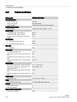
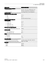
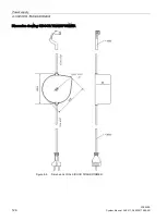
Page 115: ...ximum A 3 5 Apparent power consumption maximum V A 650 Supplied active power maximum W 100 limited to 2 s W 540 Efficiency at 100 W active power output at 230 V AC 90 Operating resource protection class I Overvoltage category 2 Output voltage at DC Rated value V 36 Output voltage at DC Rated value Note SELV Relative symmetrical tolerance of the output voltage 3 Output current minimum rated value A...

Page 116: ...ct exposure to the sun during storage C 20 70 during transport C 40 70 Relative humidity without condensation 10 93 Installation altitude at height above sea level maximum m 2 000 Protection class IP IP54 Installation mounting dimensions Mounting type Four 5 mm screws Width mm 270 Height mm 55 Depth mm 80 Standards Standard for EMC EMC Directive 2004 108 EC EN 12015 EN 12016 for safety EN 60950 1 ...

Page 117: ...500E System Manual 09 2017 A5E33917696 AD 117 Dimension drawing of SIDOOR NT40 Safety plug Cable length approx 1 5 m Cable length approx 2 m Controller connection X3 LED Power ON Figure 8 3 Dimensions of switch mode power supply NT40 ...

Page 118: ...ination with the Product combinations Page 21 controllers specified Other loads must not be connected to the output connector Design Schuko plug 220 240V 10 50 60 Hz Length approx 2 m Connector for connection to the controller Length approx 1 5 m Height of the mains transformer approx 65 mm width approx 145 mm depth approx 126 mm Diam 6 1 mm Size 10 L 70 mm Figure 8 4 SIDOOR TRANSFORMER ...

Page 119: ... 119 Function The SIDOOR TRANSFORMER is a 220 240 VAC 10 50 60 Hz standard power supply unit for supplying SIDOOR controllers without an integrated power supply Output line The output line is connected to slot X3 of the SIDOOR controller The pin assignment at slot X3 is as follows ...

Page 120: ...rcuit breaker to IEC60898 1 10 A tripping characteristic C or 6 A tripping characteristic D for example 1 pole miniature circuit breaker 5SY4110 7 or 5SY4106 8 Installation must be performed in accordance with VDE0100 and VDE 0160 CAUTION Risk of fire The transformer housing temperature can rise to over 105 C in the event of a fault in the controller or a short circuit in the output line of the tr...

Page 121: ...MER ATE500E System Manual 09 2017 A5E33917696 AD 121 Procedure Proceed as follows to install the transformer 1 Drill the hole for the screw as shown in the dimension drawing 2 Secure the transformer with 1 M6 screw at least 70 mm long ...

Page 122: ...tting and commissioning of the controller and its associated components in Section Connection and commissioning Page 137 Procedure Note Risk of injury through moving mechanical parts The control system will become ready for operation after the supply line has been connected If a control signal is present the door will move in the set direction Always connect the supply lines last of all Carry out ...

Page 123: ... the power plug disconnect the connection to the SIDOOR control circuit device Inspection A B Interconnecting input lines PRI L1 and L2 N Interconnecting output cables SEC VCC GND and PE Inspection C Interconnecting output cables SEC VCC and GND and measuring against PE Table 8 1 Test voltage Test time PRI SEC A PRI PE B SEC PE C Type test 60 s 4000 VAC 4000 VAC 1500 VAC Manufacturing test 1 s 400...

Page 124: ...e range upper limit 60 Hz Mains filter integrated Yes Input current Current consumption max 1 6 A Operational current of fuse protection at input min 6 A Operational current of fuse protection at input max 10 A Tripping characteristic class of fuse protection at input D6 C10 Output voltage RMS value pulsating DC voltage at full load 17 3 V At 230 V AC RMS value pulsating DC voltage at 0 7 mA peak ...

Page 125: ...mark No direct exposure to the sun Ambient temperature during stor age transportation Storage min 20 C Storage max 70 C Transportation min 40 C Transportation max 70 C Air pressure acc to IEC 60068 2 13 Installation altitude above sea level max 2 000 m Relative humidity No condensation min 10 No condensation max 93 Cables Cable length Input side 2 m Output side 1 5 m Connection method Design of el...

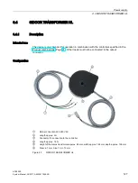
Page 126: ...Power supply 8 3 SIDOOR TRANSFORMER ATE500E 126 System Manual 09 2017 A5E33917696 AD Dimension drawing SIDOOR TRANSFORMER Figure 8 6 Dimensions of the SIDOOR TRANSFORMER ...

Page 127: ...tion with the controllers specified in the Product combinations Page 21 Other loads must not be connected to the output connector Configuration Mains connection 220 240 VAC Length approx 2 m Connector for connection to the controller Length approx 1 5 m Height of the mains transformer approx 65 mm width approx 145 mm depth approx 126 mm Diam 6 1 mm Size 10 L 70 mm Figure 8 7 SIDOOR TRANSFORMER UL ...

Page 128: ...6 AD Function The SIDOOR TRANSFORMER UL is a 220 240 VAC 10 50 60 Hz standard power supply unit for supplying SIDOOR controllers without an integrated power supply Output line The output line is connected to slot X3 of the SIDOOR controller The pin assignment at slot X3 is as follows ...

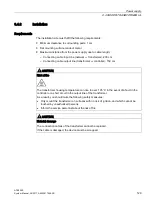
Page 129: ...cable output line transformer controller 150 cm CAUTION Risk of fire The transformer housing temperature can rise to over 105 C in the event of a fault in the controller or a short circuit in the output line of the transformer As a result you should take the following safety measures Only mount the transformer on surfaces with no risk of ignition and which cannot be touched by unauthorized persons...

Page 130: ... 130 System Manual 09 2017 A5E33917696 AD Procedure Proceed as follows to install the transformer 1 Drill the hole for the screw as shown in the dimension drawing 2 Secure the transformer with 1 screw M6 minimum length 70 mm on a flat metal surface ...

Page 131: ...ied by 2 ungrounded wires for example L1 L2 fusing has to be implemented by a 2 pole miniature circuit breaker with coupled switching element When there is a connection between an ungrounded wire L and a grounded wire N only a 1 pole miniature circuit breaker in the L branch is required Make sure that the on site customer provided fuse meets these requirements For the CE setting with a miniature c...

Page 132: ...the controller and of the associated components in the section Connection and commissioning Page 137 Note Risk of injury through moving mechanical parts The control system will become ready for operation after the supply line has been connected If a control signal is present the door will move in the set direction Always connect the supply lines last of all Carry out the following steps in the giv...

Page 133: ...ut the power plug disconnect the connection to the SIDOOR control circuit device Inspection A B Interconnecting input lines PRI L1 and L2 N Interconnecting output cables SEC VCC GND and PE Inspection C Interconnecting output cables SEC VCC and GND and measuring against PE Table 8 2 Test voltage Test time PRI SEC A PRI PE B SEC PE C Type test 60 s 4000 VAC 4000 VAC 1500 VAC Manufacturing test 1 s 4...

Page 134: ...ible range upper limit 60 Hz Mains filter integrated Yes Input current Current consumption max 1 6 A Operational current of fuse protection at input min 6 A Operational current of fuse protection at input max 10 A Tripping characteristic class of fuse protection at input D6 C10 Output voltage RMS value pulsating DC voltage at full load 17 3 V At 230 V AC RMS value pulsating DC voltage at 0 7 mA pe...

Page 135: ...ation min 20 C max 55 C Remark No direct exposure to the sun Ambient temperature during stor age transportation Storage min 20 C Storage max 70 C Transportation min 40 C Transportation max 70 C Air pressure acc to IEC 60068 2 13 Installation altitude above sea level max 2 000 m Relative humidity No condensation min 10 No condensation max 93 Cables Cable length Input side 2 m Output side 1 5 m Conn...

Page 136: ...Power supply 8 4 SIDOOR TRANSFORMER UL ATE500E 136 System Manual 09 2017 A5E33917696 AD Dimension drawing SIDOOR TRANSFORMER UL Figure 8 9 Dimension drawing TRANSFORMER UL ...

Page 137: ... in particular during the automatic determination of parameters The light barrier is not active during the learn run Increased forces speeds and energies arise in the closing and opening directions during the learn run Therefore ensure that the door is secured with physical barriers prior to a learn run and during commissioning WARNING Risk of injury during commissioning Prior to the learn run the...

Page 138: ...onnect the motor plug to slot X7 Note The X6 control inputs plug is not plugged in during commissioning in order to prevent uncontrolled movements Connecting modules optional only for controllers with the corresponding module 1 Connect the relay module Proceed as described in the Section Relay module Page 66 2 Connect the CAN module Proceed as described in the Section CAN module Page 71 ...

Page 139: ...Connect the power supply to slot X3 4 The learn run starts automatically and the learn run button can be released See Table 6 3 Starting a learn run when the supply voltage is applied Page 44 5 At the end of the learn run the 7 segment display H401 displays 0 because the digital inputs signals are not yet connected See Section Digital input signals Page 62 6 Switch off the controller by pulling ou...

Page 140: ...Bd 20 kBd 50 kBd 100 kBd 125 kBd 250 kBd 500 kBd 800 kBd 1000 kBd Door number 1 3 Switch on the controller by connecting the power supply to the controller and to the network 4 The four LEDs alongside the plug connector X6 indicate which control signal is currently active If there is no obstruction in the range of movement of the door the LED for the LIGHT BARRIER DCPS is lit continuously 5 If the...

Page 141: ...n the closing direction must not exceed 10 joules According to EN 81 the maximum kinetic energy of the door must not exceed 4 joules in the closing direction if the reversing device is disabled and every closing operation must be signaled acoustically An acoustic signal is not part of the SIDOOR system and must be provided and ensured by the operator Gearing up or down is not allowed on the toothe...

Page 142: ...WARE optional part of the SIDOOR SOFTWARE KIT see section Optional additional units Page 18 Simple settings can also be made with the three service buttons and the 7 segment display on the controller See Section Using the minimal editor Page 46 The parameter changes are always accepted by the controller in normal operation when the door is stationary Note Record the determined optimal parameter se...

Page 143: ...0E System Manual 09 2017 A5E33917696 AD 143 Additional units 10 10 1 SIDOOR SERVICE TOOL 10 1 1 Description Overview Connection plug to connect the SIDOOR SERVICE TOOL to the controller Display Control keys ...

Page 144: ...OOR SERVICE TOOL Procedure CAUTION Material damage resulting from improper use A SIDOOR controller or the device it is connected to may be damaged by using slot X8 to connect to fieldbus systems such as CAN PROFIBUS or Modbus You should therefore only connect suitable SIDOOR accessories to slot X8 SIDOOR Service Tool plug type connector D SUB connecting cable socket type connector D SUB connecting...

Page 145: ...neral setup Profile parameters Note If the SIDOOR SERVICE TOOL is in the Quick setup or General setup menu the door commands of the controller are blocked by the command inputs of the terminal strip X6 Key functions Key Description Function Return key Jump to next menu below or accept a parameter value Escape key Jump back to menu above Menu selection key Increases a parameter value Menu selection...

Page 146: ...lect next parameter See step 1 Exit menu Parameter changes Note Parameter changes are accepted with the door at a complete stop or in the OPEN or CLOSED position WARNING Risk of injury due to moving mechanical parts After parameters have been changed the permitted energies and forces have to be checked by service staff and adjusted if they exceed their limit values This has to be done on the heavi...

Page 147: ... 4 Technical specifications Article number 6FB1105 0AT01 6ST0 General information Product brand name SIDOOR Product designation SIDOOR SERVICE TOOL Product version Diagnostic and parameterization tool Cables Cable length of the connection cable 2 m Dimensions Width 65 mm Height 100 mm Depth 25 mm ...

Page 148: ...09 2017 A5E33917696 AD Appendix A A 1 Profiles and adjustment ranges A 1 1 Profile name Profile SIDOOR MED280 1 M6 default profile 2 M6 min profile 1 3 M6 min profile 2 4 M6 max profile 1 5 M6 max profile 2 6 M6 special profile ...

Page 149: ...60 40 50 60 70 50 Cutter speed CLOSE mm s 40 40 50 60 70 50 Initial speed CLOSE mm s 90 50 60 70 90 60 Nudge speed CLOSE mm s 150 100 100 150 150 100 Acceleration ramp OPEN mm s2 2200 800 1000 2500 3000 3000 Braking ramp OPEN mm s2 800 600 800 1000 1200 1200 Reversing ramp OPEN CLOSE mm s2 1200 600 800 1000 1200 1200 Acceleration ramp CLOSE mm s2 800 600 800 2500 2500 500 Braking ramp CLOSE mm s2 ...

Page 150: ...30 90 Initial speed OPEN mm s 30 90 Maximum speed CLOSE mm s 100 500 Creep speed CLOSE mm s 30 90 Cutter speed CLOSE mm s 30 90 Initial speed CLOSE mm s 30 90 Nudge speed CLOSE mm s 50 250 Acceleration ramp OPEN mm s2 300 3000 Braking ramp OPEN mm s2 300 1200 Reversing ramp OPEN CLOSE mm s2 300 1200 Acceleration ramp CLOSE mm s2 300 3000 Braking ramp CLOSE mm s2 300 1200 Reversing ramp CLOSE OPEN ...

Page 151: ... supply Note Parameter changes Parameters should always be adjusted during normal operation with the door in the CLOSED position because the controller then accepts the values immediately Parameter Unit Set value Slow end distance OPEN mm Slow start distance OPEN mm Slow start distance CLOSE mm Slow end distance CLOSE mm Maximum speed OPEN mm s Slow end speed OPEN mm s Slow start speed OPEN mm s I...

Page 152: ...ramp OPEN mm s2 Reversal ramp OPEN CLOSE mm s2 Acceleration ramp CLOSE mm s2 Deceleration ramp CLOSE mm s2 Reversal ramp CLOSE OPEN mm s2 Idle torque power OPEN A Idle torque power CLOSE A Peak torque close A Static force limit open N Static force limit close N Limit force end CLOSE N Static nudge force CLOSE N Special parameter Set value Command input CANopen node ID Baud rate Door number Input 1...

Page 153: ...on service support gives you direct access to information about products systems and services as well as a large number of programming configuration and application examples Furthermore the Online Support portal gives central access to further Services and contact persons http www siemens com automation partner Technical Support Expert advice on technical questions with a wide range of demand opti...

Page 154: ...cations 86 Versions 14 Counterweight 80 Cutter press on torque 79 D DCPS 25 DOOR CLOSE 27 DOOR OPEN 28 Drive functions 23 Driving curve 78 E Emergency release 38 F Faults 82 Force obstruction detection 31 H H401 43 82 L Learn run During operation 39 When the supply voltage is applied 39 Learn run button 43 Light barrier 24 M Minimal editor 42 42 46 Activation 47 Deactivation 49 Selecting a profile...

Page 155: ...SIDOOR NT40 108 117 Connection and commissioning 113 Design 108 Input line X1 109 Installation 111 Output line X2 110 Technical specifications 116 SIDOOR Service Tool Technical specifications 147 SIDOOR SERVICE TOOL 143 Connection 144 Key functions 145 Menu navigation 146 Operating principle 146 Operation 145 SIDOOR TRANSFORMER 118 126 Design 118 Output line 119 SIDOOR TRANSFORMER UL 136 Speed lim...

Reviews: