Connection and commissioning
ATE500E
140
System Manual, 09/2017, A5E33917696-AD
Final settings
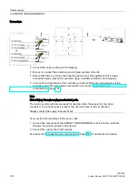
1.
Set LB or DCPS
Activate the connected signal (LB or DCPS) via the SIDOOR SERVICE TOOL in the
following entry:
MAIN MENU > General setup > Special parameters > Inp. 1
2.
Activate the CAN interface (optional, only with ATE500E CAN)
Activate the CAN interface by selecting the following settings via the SIDOOR SERVICE
TOOL:
"MAIN MENU > General setup > Special parameters >
...
–
Command input:
CAN
–
Load default CAN parameters
–
CANopen node ID:
7
–
Baud rate:
Automatic, 10 kBd, 20 kBd, 50 kBd, 100 kBd, 125 kBd, 250 kBd, 500 kBd,
800 kBd, 1000 kBd
–
Door number:
1
3.
Switch on the controller by connecting the power supply to the controller and to the
network.
4.
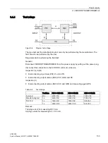
The four LEDs alongside the plug connector X6 indicate which control signal is currently
active. If there is no obstruction in the range of movement of the door, the LED for the
LIGHT BARRIER / DCPS is lit continuously.
5.
If the control signal CLOSE is present, the door moves into the CLOSED position at initial
speed.
If an OPEN control signal is present, the door moves into the OPEN position at initial
speed.
6.
Once the controller has detected the door OPEN and CLOSED end positions, the
subsequent opening and closing movements proceed at normal speed once again.

