


Power supply
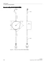
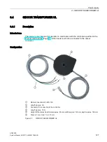
8.4 SIDOOR TRANSFORMER UL
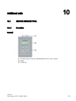
ATE500E
132
System Manual, 09/2017, A5E33917696-AD
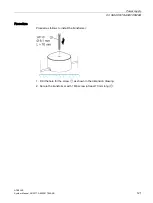
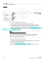
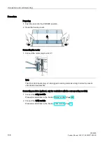
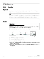
Procedure
●
Connect the wires as shown in the drawing.
●
Be sure to connect the protective ground (green-yellow) correctly.
●
Ensure that there is a mains disconnecting device near the equipment that is easily
accessible clearly marked (for example, using a suitable miniature circuit breaker).
●
You can find a description of the complete electrical setting and commissioning of the
controller and of the associated components in the section Connection and
commissioning (Page 137).
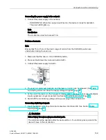
Note
Risk of injury through moving mechanical parts.
The control system will become ready for operation after the supply line has been
connected. If a control signal is present, the door will move in the set direction.
Always connect the supply lines last of all!
Carry out the following steps in the given order:
1.
Connect the output line of the SIDOOR TRANSFORMER to slot X3 on the controller.
Observe the polarity printed on the device.
2.
Connect the supply line to the network.
See the section Connection and commissioning (Page 137) for additional information.


