Operations- Ground Fault Sensing Schemes
Ground Fault Sensing Scheme
The following are brief descriptions of the ground fault
sensing schemes as they relate to the Siemens Electronic
Trip Unit. Detailed technical and application information
of the ground fault sensing schemes is contained in NEMA
Standard No. PB 2.2 "Application Guide for G round Fault
Protective Devices for Equipment".
Residual (3-Phase, 3-Wire) Under normal system condi
tions (without g round fault), the vector sum of the phase
currents being monitored by the trip unit is zero. This is also
true under the condition of an overcurrent phase-to-phase
fault and phase-unbalance condition. When a phase-to
ground fault occurs, the vector sum of the phase currents
is directly proportional to the magnitude of the fault. The trip
unit's microprocessor uses this vector sum data in the
execution of the ground fault protection function. The trip
unit utilizes the internal breaker current transformers. No
external current transformers are required .
Residual (3-Phase, 4-Wire). In the 3-Phase, 4-Wire Resi
dual scheme a fourth current transformer is connected in
the neutral conductor to "Sense" normal neutral currents.
Under normal system conditions the vector sum of the
currents in all phases equals the neutral current. This is also
true under the condition of an overcurrent phase-to-phase
fault and phase-unbalance condition. When a phase-to
ground fault occurs, the fault current returns via a path other
than the neutral. Therefore, the vector sum of the phase
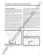
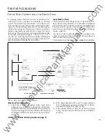
Residual Sensing. Circuit Breaker Wiring for Ground Protection
(3-Phase, 4-Wire System Shown).
currents no longer equals the neutral current. This current
differential is detected by the trip unit and used in the
execution of the ground fault protection function.
Source Ground. In this scheme, the phase currents are not
used in detecting and processing ground faults. The trip
unit executes the ground fault protection function based on
data from a ground current sensor. This sensor is located
on the neutral connection to ground at the service entrance,
and is connected to the neutral transformer input terminals
on the trip unit.
Zero Sequence. This scheme is very similar to the Residual
Schemes. A core balance type current sensor encircles all
phase conductors and neutral on a 4-wire system. Under
normal system conditions or a phase-to-phase fault condi
tion, there is no output from the sensor to the trip unit
because the vector sum of the currents through the sensor
window is zero. If a ground fault occurs, the ground current
is not seen by the sensor, which returns to the source by a
path other than through the sensor window. The sensor
detects this current unbalance and provides the data
required by the trip unit to execute the ground fault protec
tion function. The zero sequence sensor is connected to the
neutral transformer input on the trip unit.
NOTE: For Neutral Sensor installation, see pages
67-68.
Neutral D1sconnect L1nk
Maw.
Source Ground Current
\
Ma1n
Neutral
I
I
I
I I
I
-
I
Neutral D1sconnoct L1nk
Zero Sequence Ground Fault Protection.
33
www
. ElectricalPartManuals
. com


