Internal Accessories
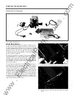
Electric Motor Op erator
Motor Operator
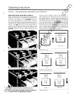
� Mechanism Plate
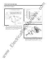
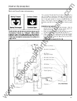
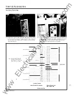
3.) Install the Motor Operator Assembly on the mechanism
plate with the three #1 0
x
1
/
4"
screws. Align the keyway of
the charging shaft with the keyway of the charge arm. All
mounting screws are Long-Lok' self -locking screws. (Torque
screw to 25-32 in. lbs.).
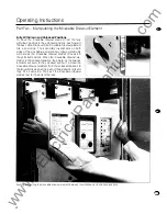
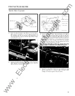
4.) Locate and slide the Remote Close Lever on the Closing
0
Shaft located on the Mechanism. Secure the Lever by
tightening the Set Screw to 6-8 in-lbs.
-�--
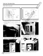
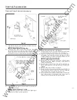
Handle Check Switch
Latch
Check Sw1tch
//--- Remote Close Soleno1d
_
..
------- #1 0-32
x
3/8''
Screw
#6-32 x
1/4"
Screw
---...___
Soleno1d Bracket
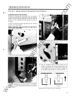
5.) Locate the Remote Close Solenoid. Remove the Handle
Check Switch from the Solenoid Bracket Mount the Remote
Close Solenoid to the mechanism plate. Make sure that the
Solenoid Plunger is seated inside the Solenoid. Secure the
assembly with the #6-32
x
W'
screw (torque to 9-10 in-lbs)
and #1 0-32
x
3fs
screw (torque to 25-32 in-lbs). Reattach
the Handle Check Switch to the Solenoid Bracket with the
#4-40
x
1
/
2
screws (torque to 4-6 in-lbs).
NOTE: If the handle check switch was removed from the
solenoid bracket, it should be re-installed at this point.
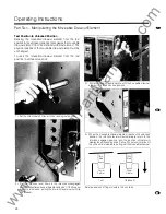
6.) Attach the Latch Check Switch on the mechanism plate
with the two #6-32
x
1
/
4"
screws. Adjust the switch while
holding the Actuator against the switch body.
39
www
. ElectricalPartManuals
. com

