background image

Operations- Functions and Adjustments 

Part Three- Monitoring  the Electronic Trip Unit 

General  Instructions 

The trip unit executes  its overcurrent protection functions 

based  on  the  rating  plug  value  and  the  settings  of  the 

current adjustments.  Therefore,  care should  be taken  by 
the user to make proper selections and settings. 

An  adjustment  will  automatically  revert  to  its  minimum 

possible setting whenever  a change to the adjustment is 
being made. This may cause inadvertent tripping of the 
breaker if the adjustment is made with the  breaker in  the 

closed  position. Therefore,  Siemens recommends that all 
adjustment changes be made with the breaker open. 

To set an adjustment, place a slotted screw driver onto the 

point-to-point adjustment switch and rotate the switch to the 
desired setting. 

The figure on the following page describes the region of the 
time current curve  that is  being  effected  by each  adjust­
ment 

For complete information on setting the  individual adjust­
ments see the  Information  and  Instruction  Guide  for  the 

Electronic Trip Unit,  Bulletin 2.20-3A  For time current trip 

curves contact your local Siemens sales office. 

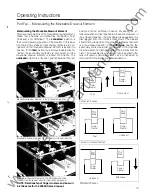
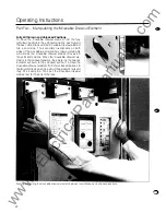
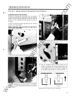
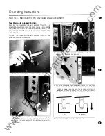
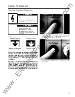
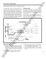
4000A Electronic Trip Unit (Photo of 2000A shown for illustration 

purposes only) 

27 

www 

. ElectricalPartManuals 

. com 

Summary of Contents for SB Series

Page 1: ...SIEMENS SB Encased Systems Breakers 4000 Ampere Frame Rating Information and Instruction Guide Bulletin 2 20 5A 6 f w w w E l e c t r i c a l P a r t M a n u a l s c o m ...

Page 2: ...ied person is one who is familiar with the installation construction or operation of the equipment and the hazards involved In addition he has the following qualifications a is trained and authorized to de energize clear ground and tag circuits and equipment in accordance with established safety practices b is trained in the proper care and use of protective equipment such as rubber gloves hard ha...

Page 3: ...t Element 9 Control Terminal Blocks 62 64 Installing the Moveable Drawout Element 1 0 Sliding Secondary Disconnects 65 Installing Fixed Mounted Circuit Breakers 1 1 T Connectors 65 Installing the Electronic Trip Unit 12 14 Neutral Current Transformer 66 68 Inserting Removing Rating Plug 14 15 Lifting Bracket 69 Rating Plugs 70 Operating Instructions Display Module 70 Part One Operating the SB Enca...

Page 4: ...breakers in industrial plants large commercial complexes and medical and health care facilities The circuit breakers are constructed for either fixed or drawout installation They can be physically grouped in central distribution switchboards or used separately in stand alone applications The SB breaker is equipped with a two step stored energy mechanism for closing and opening the breaker contacts...

Page 5: ...ting rating for the SB breaker Overcurrent Protection Configurations Siemens Electronic Trip Units for SB breakers are avail able in six basic overcurrent protection configurations to meet specific protection requirements All trip units come equipped with Adjustable Continuous Current and Long Time Delay functions Optional protection configura tions are Protection Configuration Long Time Short Tim...

Page 6: ...re con ventional construction The electrical insulation property of the thermoset material enhances the safety of operation The insulated case physically isolates and electrically insulates the user from the internal high voltage contacts The arc chambers and main contact structure are encased in the back compartment The trip unit controls springs of the stored energy mechanism and optional intern...

Page 7: ... Frame Fixed Mounted 1 00 of the frame rating 66 sq in ventilation is required in top and bottom of front cover for the 4000A frames Detailed outline drawings of the breakers and drawout elements are included in the Outline Dimensions section pages 74 79 Example One 1 4000ASiemensSB Encased Systems Breaker can be mounted in a 90 inch switchboard w1th the top sect1on reserved for metering 5 w w w E...

Page 8: ...ed energy mechanism Once the breaker is closed the mechanism can be recharged The breaker is now prepared for a rapid open close or open close open operation Main stored energy springs located in the front compartment 6 Centralized Controls The manual charging handle pushbutton control switches and color coded indicators are grouped in the central escutcheon on the front cover The U shaped constru...

Page 9: ...veable drawout element is disengaged from the racking mecha nism The moveable drawout element can be easily pulled between the unlocked position and the withdrawn position A color coded indicator displays the position of the move able drawout element In additiontothe integral pump handle two levers are used to control the movementofthemoveable drawoutelement A single interlock lever automatically ...

Page 10: ...antaneous LSI Long Time Short Time Ground Fault LSG Long Time Instantaneous Ground Fault LIG Long Time Short Time Instantaneous Ground Fault LSIG As standard features the trip unit has two built in test functions and a fault identification function System Check is a built in test function that continuously checks the status of the microprocessor and protective algorithms A green LED on the front p...

Page 11: ...ion rails in place Depending upon the installation scheme it may be necessary to remove the tie wraps on the extension rails just prior to securing the stationary drawout element in the switch board If the stationary drawout element is secured to a pallet remove the securing device The bottomofthe stationarydrawoutmustbe securedtothe switchboard using four 4 3 s bolts Additional mounting hardware ...

Page 12: ...ted If lifting straps are used instead of the lifting device accessory the lifting straps should go between the primary contacts In either of these arrangements the moveable drawout ele ment may be balanced as it is being lifted by a crane or hoist The moveable drawout element should not be lifted Lift by using rear guide posts one on left side and one on right side Lift the moveable drawout eleme...

Page 13: ...he SB breaker in accordance with the outline drawings at the end of this section The outline drawing forthe 4000Aframe is located on pages 74 79 The locations of the mounting holes and the recommended screws are depicted on the drawing All eight mounting screws will be used to secure the breaker to the switchboard Carefully uncrate the breaker and remove all packing material The keys for a breaker...

Page 14: ...ged as shown above Personal injury or mechanical damage may occur Check to see that the breaker is open before inserting or removing a rating plug The breaker should always be in the open position when there is not a rating plug in the trip unit 1 Remove the trip unit screws that hold the transparent cover Th rating plug and adjustmentsonthefrontpanelofthetrip unit are protected by a transparent c...

Page 15: ...g the need tor screws or latches To remove a rating plug squeeze the clips and pull the plug from the plug receptacle Since the plug is held in place by compression some force will be required to Q e ug Do not los the breaker with the rating fl j 5 To replace the cover bow slightly in the middle and snap 1nto place After the rating plug has been inserted and th tt d e necessary se lng a justments ...

Page 16: ... key interlocks and other locking devices Discharging energy in the stored energy mechanism 18 Closing the SB Breaker Locally Before the breaker can be closed the stored energy mechanism must be fully charged and all of the closing prevention devices and accessories must be in the non inhibiting state or position In this condition all that is required to close the breaker is to push the Close push...

Page 17: ...ion 2000A frame drawout used for illustration purposes NOTE Relationship of finger clusters and bus Will be the same for the 4000A frame drawout position and the withdrawn position Physically the un locked position and test position are the same However in the unlocked position the moveable drawout element is disengaged from the interlock mechanism The breaker should not be tested when the moveabl...

Page 18: ...ill mate as the moveable drawout element moves into the unlocked position When the moveable drawout ele ment is in the unlocked position the pointer on the position indicator will point to the unlocked symbol To move the moveable drawout element from the unlocked position to the fully withdrawn position pull out the extension rails until they hit a solid stop Then pull the moveable drawout element...

Page 19: ...ing in position 2 Pull the interlock lever down to the interlock disengaged position Illustratedbeneath padlockdevice If the breaker contacts are closed pulling the interlock lever down Will tnp the breaker 3 Pump the racking pump handle until the moveable drawout element has reached the test position 4 When the moveable drawout element reaches the test position the interlock lever will automatica...

Page 20: ... to the interlock disengaged position Illustrated beneath padlock device Ifthe breaker contacts are closed pulling the interlock lever down will trip the breaker 26 3 Pump the racking pump handle until the moveable drawout element is in the unlocked position 4 When the moveable drawout element reaches the unlocked position the interlock lever will automatically return to the interlock engaged posi...

Page 21: ...the breaker in the closed position Therefore Siemens recommends that all adjustment changes be made with the breaker open To set an adjustment place a slotted screw driver onto the point to pointadjustmentswitch and rotatetheswitchtothe desired setting The figure on the following page describestheregion ofthe time current curve that is being effected by each adjust ment For complete information on...

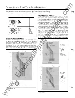
Page 22: ...ing to the current value selected on the Short Time Pickup adjust ment There are two modes of operation of this adjustment on all Siemens Electronic Trip Units one is afixed delay the other is an inverse l2t ramp delay The 12t Delay has the characteristic of being inversely proportional to the square of the magnitude of the overcurrent condition This means that higher overcurrent conditions have s...

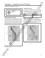
Page 23: ...ride On all trip units an instantaneous override function has been provided It is setnominally at the short time rating of the respective breaker frame size This allows the breaker to ride through high faults up to its short time capability however it is self protecting above these values Breaker Short Time kA Rating Frame Size 500 seconds max 800A 25 2000A 35 4000A 65 Discriminator Circuit Making...

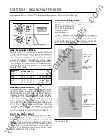
Page 24: ...e setto 1 2 3 4 or 5 seconds In the inverse l2t ramp delaymode the delaymaybe settoacalibratedvalue of 1 2 3 4 or 5 seconds at a current equal to 0 5 times the frame ampere rating ln The inverse 12t ramp delay reverts to afixed delay of the same value when the ground current lg exceeds 50 percent of the frame rating In Ground Fault Memory Circuit All Siemens Electronic Trip Units with ground fault...

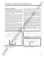
Page 25: ...utral Therefore the vector sum of the phase Residual Sensing Circuit Breaker Wiring for Ground Protection 3 Phase 4 Wire System Shown currents no longer equals the neutral current This current differential is detected by the trip unit and used in the execution of the ground fault protection function Source Ground In this scheme the phase currents are not used in detecting and processing ground fau...

Page 26: ...es the most recent event 34 Integral Test Modes The integral testfunction enables the user to exercise the trip unit electronics the magnetic latch and the breaker mechanism The purpose of the integral test function is to provide the user an easy means to conduct a go no go type test before bringing the breaker on line After the breaker has been brought on line it may be used during routine inspec...

Page 27: ...le circuit breaker is in service turn off and lockout power supplying the circuit breaker prior to cover removal and accessory installation NOTE The accessory installation procedures out lined in this bookletare general bynatureandmaynot contain the latest up to date information for com plete installation Therefore it is Siemens recommen dation that all accessories be installed utilizing the instr...

Page 28: ...rners and the 4 W Phillips head screws in recesses in cover 4 Remove cover 36 5 Remove the trip unit if installed by removing trip unit retaining screw 6a Slide the trip unit up to clear the support bracket pins b Remove the trip unit by pulling the trip unit away from the trip unit plug w w w E l e c t r i c a l P a r t M a n u a l s c o m ...

Page 29: ...r Siemens SB breakers are presented in this section The accessories are divided into two groups accessories that are installed in the front compartment of the circuit breaker Internal Electric Operator Troubleshooting Guide Symptom Solutions Motor does not run 1 Check for spnngs already charged by checking spring charge indicator 2 Check for rated voltage at LT1 and LT5 3 Check motor fuse requires...

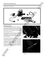
Page 30: ...onentsofthe electric operator are installed on the left side The motor fuse is accessible from the front panel The principal components of the electric operator are a charging motor motor controller gear box cam mecha nism closing solenoid motor fuse and check switches to monitor the positions of the mechanical components The charging motor gear box and cam mechanism are integrated into a single a...

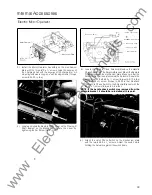
Page 31: ...rew ___ Soleno1d Bracket 5 Locate the Remote Close Solenoid Remove the Handle CheckSwitch from the Solenoid Bracket Mountthe Remote Close Solenoid to the mechanism plate Make sure that the Solenoid Plunger is seated inside the Solenoid Secure the assembly with the 6 32 x W screw torque to 9 10 in lbs and 10 32 x 3fs screw torque to 25 32 in lbs Reattach the Handle Check Switch to the Solenoid Brac...

Page 32: ...switchActuatorandtheLatch Lever Tighten screws to 9 1 1 in lbs Check adjustment after tightening screws and readjust if necessary 40 Slot Latch Tab 8 Plug LT6 and LT7 Connectors into the Connector Strip until latchtabssnap intoslots Gentlypullwirestoensuretheyare latched into the Connector Strip Motor Operator Assembly 6 32 X 1 4 6 Lockwasher ECMC Assembly 9 Install the Electric Motor Controller E...

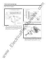
Page 33: ...Connect the RC Connector and RC Connector to the Remote Close Solenoid 1 1 Install the B Switch assembly on the reset mechanism assembly Make sure to install the Insulator between the Switch and metal bracket Securethe assemblywith the two 4 40 x 1 2 screws Torque screws to 4 6 in lbs Check to be sure the Actuator fits into the slot in the push link and does not bind 12 Route the two wires attache...

Page 34: ... replacing the mounting screw Torque 42 screw to 6 8 in lbs Screw Fuse Hole Plug 18 Before replacing the breaker cover remove the fuse hole plug from the inside of the cover as illustrated above Also cut out the Fuse not installed area of the rating label 19 Replace front cover see page 14 being careful not to pinch the wires that are routed to the secondary discon nects or terminal block 20 Repla...

Page 35: ... 1 4 PHMS 10 10 32 UNC 28 x 3 8 PHMS Slide lever on to shaft when installing solenoid assembly After tightening solenoid screws align linkage with solenoid plunger and tighten set screw against shaft C L 1 1 6 32 UNC 28 x 1 4 PHMS 12 4 40 UNC 28 x 1 2 PHMS 13 6 Lockwasher 14 6 32 UNC 2B x 1 4 PHMS 15 6 32 UNC 28 x 1 4 Type F CPHS 16 Cable Tie 17 Local Close Switch Assembly 18 19 Wire Tie Adhesive ...

Page 36: ... 0 5 Amps Max 200 Vdc Max LT2 Remote Close NO j NC LEC COM ____ Local Electric LT3 Local Electnc Close Close Sw1tch _ _ _ _ _ _ _ _ _ _ v a e s a to y s ll d p o O y _ _ _ _ _ _ _ _ _ I Local Electric Close _l f_1_ _ _ Eiec Oper __ _ LT2 Rem Close LT3 Local Electric Close LT4 Spnng Ch lnd L T5 COMMON I Factory Installed Jumper Wtre 1 1 Thts Wire Is Not I s t n ECI L LBb C L l1 C Note Customer May ...

Page 37: ...lled Local Electric Close Solenoid as noted on page 44 Installation Instructions 1 Remove rubber band from the solenoid plunger Slide the remote close lever on to the closing 0 shaft but do not tighten the set screw at this time see figure 1 2 Place the return spring over the solenoid plunger and slide the solenoid over the solenoid plunger see figure 1 3 Attach the remote close assembly to the me...

Page 38: ... Bracket Pusher Link B Switch Figure 4 8 Locate the reset mechanism see figure 5 9 Tomountthe B switch first makesurethattheswitch lever is inside the top cavity of the pusher link see figure 4 1 0 Make surethattheswitch lever restsonthepusher linkwhen the breaker main contacts are open see figure 4 Place insulator between B switch and bracket Secure the B switch with the 2 4 screws provided NOTE ...

Page 39: ... Connection RC Latch Check Switch Assembly Mechanism Plate B Switch Connection LC 8 Cable Tie Mount r LT2 LT4 Mid barrier Figure 5 RC Figure 6 Reset Mechanism B Switch 4 Screw Cable Tie Mounts Cable Tie Typ 47 w w w E l e c t r i c a l P a r t M a n u a l s c o m ...

Page 40: ...ustomer r 1 L T3 Lo alEle tr Qo e I LEC COM I 1 Close Sw1tch NO NC I Local Electric i 1 LT3 Remote Close 1 I Local Electric Close I 1 Available as factory Installed opt1on only _ _ _ _ _ _ _ _ _ _ _ _ _ _ _ _ j COM LC B COM LC Latch Check Sw1tch s Type NO NC T Cleanng Switch r t U 3_ _ C o i i_ __ __ __ __ __ RC _ External Connections Internal Breaker Clos1ng Coil Remote Close WithoutChargingMotor...

Page 41: ...witches should be installed prior tothe SB breaker being installed in the switchboard Before starting the installation the breaker should be in the open position and the stored energy mechanism should be discharged A drawout constructed SB breaker already installed in the switchboard should be placed in the fully withdrawn position to allow access to the secondary disconnects The auxiliary switche...

Page 42: ... 1 Aux 5 A _ __ _ _ _ _ _ L__ c RT6 5_ A _ _ _ _ _ _ Auxiliary Sw1tch 5 RT7 1 Aux 5 8 1 L___ _ _ RT8 1 A_ u_ x _ 5 _8 _ _ _ _ Note i i lf i t r l i r Aiarm Switch Or Local Load Monitor Relay Is Installed Auxiliary Switch 6 1 RT9 RT10 1 RT RT12 RB1 I Auxiliary Switch 1 R82 I I R83 I 1 1 1 R84 R85 R86 7 R87 Auxiliary Switch_ 2_ _ _ R88 I I R89 I R810 L c o L_ C Auxiliary Switch 3 1 I R81 1 R812 Auxi...

Page 43: ...trip solenoid is installed on the right side of the front compart ment behind the trip unit and beneath the reset plate Notes I Wire markings are shown in brackets like this 2 LT indicates left top terminal block or secondary connector If practical the UVR should be installed prior to the SB breaker being installed in the switchboard Before starting the installation the breaker should be in the op...

Page 44: ...log Number Hold in Current Amperes Coil Voltage SB4UV12 12 12V de SB4UV24 06 24V de SB4UV48 03 48V de SB4UV125 02 125V de SB4UV120 02 120V ae SB4UV240 02 240V ae SB4UV480 02 480V ae SB4UV600 02 600V ae Wire terminations on terminal block or secondary disconnect arc shown below Monitored Source DC Undervoltage Release Schematic I I I LT9 UVR I I I I I I I I UVR I I Coil I I LT10 UVR I I I I Interna...

Page 45: ...Supplied by Customer r External Breaker Connections 1 Align threaded mounting holes in shunt trip with holes in reset mechanism 2 Maneuver the switch to the bottom side of the switch mounting bracket Make sure the switch actuator is resting at the end of the upper groove in the reset arm 3 Route the wires across the mechanism between the shield and mid barrier From left side of the breaker connect...

Page 46: ...condary Latch See Detail B Below Check For Bmd1ng After T1ghten1ng 8 Screws By Press1ng Down On Top Of Plunger To Operate Secondary Latch 0 Shunt Tnp Assembly 4 40 Nylok Screw Wire Guide M1dbarrier Note Mechanism Not Shown For Clarity Push here to check for binding after tightening 8 screws Plunger should move freely and be freely returned by secondary latch Secondary Latch Fork Insert w1res into ...

Page 47: ...ntact is a latching type and remote reset capability is provided To install the bell alarm first remove the breakerfront cover and trip unit if previously installed see page 36 1 Align bell alarm mounting holes as shown 2 With a small screwdriver press in tab on right side of 36 pin trip unit connector and release from mounting bracket 3 Connect bell alarm lead wires 1 and 22 to correspond ing num...

Page 48: ... I 1 1 J Q GJ GJ I I L__ 1 1 ___ 60VA Max c 0 CC G 1 SBDMR Display Module Relay 1 25A Max I_L_ _ _____J Local Load Monitor Relay 1 50Vdc 200Vac Max I i Trip Unit See Sheet 6 For All Other Trip Unit Connections _ Note Trip Unit Plug Shown As Viewed From Front Of Breaker Note Electronic Alarm Switch Local Load Monitor Relay And Remote Indicator Panel Are Mutually Exclusive No Combination Of These De...

Page 49: ...e other breaker in the open tripped position The interlock device is available for fixed mounted breakers installed side by side or in the same vertical section On drawout configured breakers the interlock device is available for breakers installed in adjacent cubicles either vertically or horizontally The mechanical interlock device is not field installable Padlock Device on Breaker A padlock dev...

Page 50: ...crews as provided Drawout padlock device kit Padlock device is installed above the interlock lever 58 Close Blocking Device on SB Breaker A close blocking device is used to prevent local closeofthe breaker under normal operating conditions The device is a cover that mounts over the push to close pushbutton blocking normal access to this switch A small hole in the centerofthecover provides a meanst...

Page 51: ...acts Closed when the moveable draw out element is in the test unlocked or withdrawn position Open when the moveable draw out element is in the connected position A maximum of four A and 8 cell switches may be installed in a breaker The switch contact ratings are given in the following table Switch Contact Ratings Supply Voltage Ampere Rating 120 VAC 10 Amps 240 VAC 10 Amps 480 VAC 6 Amps 24 VDC 3 ...

Page 52: ...the withdrawn to the un locked position 60 The drawout safety shutters kit consists of two shutter assemblies and mounting hardware The shutters are symmetrical so that either shutter can be used to cover the line or load stabs The shutters are installed on the sides of the stationary drawout If practical the drawout safety shutters should be installed priortothe stationarydrawoutelement being ins...

Page 53: ...hutter springs zinc silver spring is used on top shutter white springs are used for the bottom shutter Installation of the bottom shutter is similar to the top 6 Top left shutter assembly installed 7 Drawout safety shutters shown installed 8 Install four 4 plate extensions to the rear of the moveable drawout breaker Extension plates must be flush with the left and right mechanism plates top and bo...

Page 54: ...Disconnects terminal points 62 Control Terminal Block mounted on fixed mounted breaker Control Terminal Blocks Control terminal blocks provide electrical access to the internalaccessoriesandtrip unitofafixed mountedbreaker A breaker can be equipped with up to four control terminal blocks each with 1 2 terminal points The terminal blocks accept 1 2 AWG user wiring They are rated for 600 volts appli...

Page 55: ...k Mounts Mounting of Terminal Block Mount Catalog Numbers SBTBM 1 Accessory installation should be completed before the breaker is mounted and connected If breaker is installed turn off and lock out all power supplying the circuit breaker when installing any internal or external accessories 2 Installation of this device does not require removal of the breaker cover 3 Remove the four 4 Phillips hea...

Page 56: ...nsert the Terminal Block Assembly as shown in Figure 2 NOTE Each Terminal Block Assembly contains four Terminal Blocks and one label 3 To ensure proper positioning of the Terminal Block Assemblies see Figure 3 4 Insert label into the groove of the Terminal Block See Figure 2 Figure 4 Terminal Block Interlock See Fig 4 __l Terminal Block Figure 2 Terminal Block Interlock Mounting of Terminal Blocks...

Page 57: ...ut element the A block is at the top and the B block is at the bottom They are reversed on the left side B at the top A at the bottom On the right side of the moveable drawoutelement the B block is atthetop and the A block is atthe bottom Theseare also reversed on the left side A at the top B at the bottom The blocks and drawout elements are keyed to prevent improper installation Disconnects must ...

Page 58: ...nd right are with respect to the user facing the breaker The recommended terminal points for acces sories added in the field are illustrated below 66 T Connectors A DANGER Hazardous Voltage Will cause severe injury or death Do not attempt to install accessories with voltage present T connectors are used to connect power buses to the SB breakers 2000A SB20iCON T connectors with mounting hardware 1 ...

Page 59: ... line power within the immediate vicin ity to prevent the incidental or accidental contact of tools by the installer Use transformers with the following breaker frame ratings only N25SB N32SB N40SB SBS2500 SBS3200 SBS4000 Introduction This neutral sensing transformer is designedto be mounted on a bus bar with maximum dimensions of 5 00 x 1 25 Neutral Sensing Transformer Neutral sensing transformer...

Page 60: ...rounding Electrode Installation of neutral transformer Terminal Connections If secondary disconnects or terminal block has been fac tory mounted and the transformer has been properly ori ented and mounted connect transformer terminal X1 to LT1 1 and X2 to LT1 2 using 1 8 AWG stranded copper wire If lefttop secondary disconnects or terminal blocksare field added user must remove the circuit breaker...

Page 61: ...e to lift a moveable drawout element Provisions are provided on the drawout elements to attach a lifting device The attachment location allows the elements to be balanced as they are being lifted and installed The instructions for attaching the lifting devices are con tained in the Installation Instructions section Lifting Device Bracket Preferred lifting arrangement Connecting points for lifting ...

Page 62: ...depressing both the phase and ground fault test pushbuttons simultaneously Phase and ground fault pushbuttons are located on the SB Electronic Trip Unit in the integral testing section Present Current Demand This feature provides a display of the present current demands The present current demands are calculated averages over thirty 30 minute intervals The user may d isplay the most recent stored ...

Page 63: ...he receptacle 4 Replace and seal the transparent cover Auxiliary Power Supply Auxiliary Power Supply The auxiliary power supply is a plug in supply for bench test1ng the Electronic Trip Unit The supply may also be used to power the trip unit during the execution of a go no go type test before bringing the SB breaker on line see Mon1tonng the Trip Unit in the Operating Instructions sect1on The auxi...

Page 64: ...ll respond with I XXX NOT found Press any key to continue and you will be asked to enter another catalog number E If valid catalog number has been entered the TS 31 will prompt for the breaker settings The TS 31 will respond with I Enter Continuous Current Setting in If the unit being tested is a SB ENCASED BREAKER trip unit set the continuous setting to 1 00 this equals the value of the rating pl...

Page 65: ...ess ENTER to Continue or A to abort and then for the phase to test A message will then appear stating the test results For example CT Resistance Test Phase X PASSED Press any key to continue M There are additional ERROR messages which may appear on the d isplay during this operation which were not covered previously Test Not Running Check Test Cable Press enter to continue The test set has sensed ...

Page 66: ...l f 1itP P i fV I t El OFF Ell r Lifting Points Do Not Lift By Other Points 0 Ell 25 38 29 50 26 50 I nside Cradle i 6X Top 0 438 Mounting Holes _ _4X Top 0 228 Holes ___ 6X Bottom 4X Bottom Front Cover 4000 Amp Stationary Drawout Element Side View 2X 00 tl_ _ _ _ _ 1 _ 2X 6 50 2X 1 1 25 2X 2 50 0 0 0 0 Left Cradle Plate Shown j Cut Away For Clarity 3 26 1 3 50 w w w E l e c t r i c a l P a r t M ...

Page 67: ...w 2X 1 2 75 J I 16X 0281 I Front Mtg Holes 0 0 JSI 0 i t 0 0 I 0 0 I 0 0 0 0 I I I 0 I l 0 4X 15 00 I tl 0 0 I 0 0 0 s I r I I I 1 L 1 C 35 I 00 1 I 1 I 4X 8 75 I 0 0 I 0 0 0 ld 2X 1 7 50 I 4Xl oo 4x 00 0 r 0 I I 4X 7 50 t 0 1 1 0 0 0 0 _l 0 0 tq 0 0 0 I 0 0 0 ld 0 75 w w w E l e c t r i c a l P a r t M a n u a l s c o m ...

Page 68: ...drawn I I EE lL TJ m r 1 1 61 T_T ftt Te t t 0 0 0 0 0 0 0 0 0 0 0 0 0 0 0 0 0 0 ct 4000 Amp Drawout Moveable Element Side View II 6l 6l e E9 ct 1 1 50 23 00 23 28 _I r lr776_1r 1 i IF 0 D D I h a fb D 1 r J f I D r IIIII fb a 0 0 0 I t w II I I Jt ___ Lorawou Bceakec Hac t Handle die _Front Cover w w w E l e c t r i c a l P a r t M a n u a l s c o m ...

Page 69: ...w 29 50 Overall 0 I 0 I 0 I 0 0 I 0 I 50 0 _ ffi 0 I ul I r I F I f 0 D i D t I 18 18 I 4k I t r f Cover 4 85 I 0 0 0 I 0 L I 0 0 0 1 p 0 0 0 0 0 0 I Optional Panel Cutout For Trip Unit and Label Information Escutcheon Dimensions 0 1 1 f I t r 35 00 rail Ove l 0 J 0 I 0 lb I f FJ r I 0 UJ l J l j 0 0 0 l 0 0 0 I 0 0 0 0 0 0 0 I 0 0 0 0 0 I 0 la JQ 0 lf l n I 0 0 0 ld 0 77 w w w E l e c t r i c a l...

Page 70: ...r rT Escutcheon D 78 3 0 0 ol 0 25 0 0 res 0 W L3 50 4000 Amp Fixed Mounted Side View 7 D O 0 6 0 Or 1 6 50 1 25 f rr 75 Typ i t e 5 00 __fJLr e l 26 00 22 50 l 3 f 0 e l I 1 75 I i j 00 tl 3 25 0 f 0 I r 0 LL_ 1 p J I 414 9 1 3 R 1 2 Typ w w w E l e c t r i c a l P a r t M a n u a l s c o m ...

Page 71: ... 0 0 0 0 0 0 0 0 0 0 0 0 0 0 0 0 0 0 0 0 0 0 0 0 0 0 0 0 0 0 0 0 0 0 0 0 0 0 0 0 0 0 0 0 0 0 0 0 0 0 0 0 0 0 0 0 0 0 0 0 0 0 0 0 0 0 0 0 0 0 0 0 0 0 0 0 0 0 0 0 0 0 0 0 0 0 0 0 0 0 0 0 0 0 0 0 0 0 0 0 0 0 0 0 0 _ __ 1 1 63 1 2 1 3 1 2 75 4000 Amp Fixed Mounted Front View t 21 25 1 5 00 1 20 50 r fill D O 8 6 8 8 0 i 38 ro l 22 75 j 1 1 00 3 00 4 75 l 22 50 27 50 BX 0 44 Mounting Holes For 3fs 1 6 ...

Page 72: ...Short Time Ground Fault Number Rating Setting Delay Pickup Pickup Delay Pickup Delay SB25TLI 2500 X X X SB25TLS 2500 X X X SB25TLSI 2500 X X X X SB25TLIG 2500 X X X X SB25TLSG 2500 X X X X SB25TLSIG 2500 X X X X X SB32TLI 3400 X X X SB32TLS 3400 X X X SB32TLSI 3400 X X X X SB32TLIG 3400 X X X X SB32TLSG 3400 X X X X SB32TLSIG 3400 X X X X X SB40TLI 4000 X X X SB40TLS 4000 X X X SB40TLSI 4000 X X X...

Page 73: ...SB4UV240 480 VAC SB4UV480 1 2 VDC SB4UV12 24VDC SB4UV24 48 VDC SB4UV48 125 VDC SB4UV125 Auxiliary Switches Contact Configuration Catalog Number 1A 1B SB4AS2 2A 2B SB4AS4 3A 3B SB4AS6 4A 4B SB4AS8 5A 5B SB4AS10 6A 6B SB4AS12 Electronic Bell Alarm Accessory Catalog Number Voltage Bell Alarm SBBA24 24V DC SBBA48 48V DC SBBA125 125V DC SBBA120 120V AC Local Load Monitor Relay Accessory Catalog Number ...

Page 74: ...essory Catalog Number Breaker Closing Blocking Device SBBD Auxiliary Power Source For Electronic Trip Unit Accessory Catalog Number Capacitor Trip Auxil1ary Power Source SBAPM Accessory Catalog Number Capacitor Trip SBCAP Universal Trip Unit Test Kit Accessory Catalog Number Cell Switches Test Kit TS31 Accessory Catalog Number 1A 1 B 4CEL1 UL Listings and File Numbers 2A 2B 4CEL2 3A 3B 4CEL3 4A 4B...

Page 75: ...T2 Co1l RC ooaoo c Ciosing Coil Remote Close HC Handle Check Switch LC Latch Check Switch B Type Clearing Switch I Without Charging Motor Operator Monitored 1 Source__J_ I Supplied by Customer Supplied by Customer LT6 Coil 1 I B Type Clearing Switch LTS Coil Common coM NC ST I C Remote Open Closed lndrcatron o 1 1 I LT9 UVR I LT10 UVR Shunt Trip UVR Coil External Connections 1 LT9 UVR LT10 UVR DC ...

Page 76: ...losing Of The Breaker 1 1 By Replacing Factory Installed Jumper W1re W1th A Set Of External Contacts Electric Close Interlock Option 1 This W1re Is Not 1 Used When ECI Is Installed able s F _io f l olaled Ouu l rly External Connections Internal Breaker Connections v Jl j_ L SC I_ Fuse 1 3 4 A Slo Bio Electric Operator Motor Operator Wiring Diagram I I I I I I I I I Trip Unit See Sheet 6 For All Ot...

Page 77: ...t1 X2 __ _ _ _ _______ LT12 _ _ _ _ _ External Connections Breaker Right Side N PhaseVoltage 1 Note Trrp Unit Plug Shown 1 As V1ewed From Front Note Electronic Alarm Sw1tch Local Load Remote Montor Relay And Remore lnd1cator Panel Are Mutually Exclus1ve No I Comb1nat1on Of These Oev1ces Is 6r o e A a h r k n I Load Monitor Relay 1 Magnetic Red t12J I I Mechanism _ Gr_ l Mag Latch Actua ting Cen F ...

Page 78: ...uquerque Virginia Beach 91 6 631 9433 808 533 71 35 207 854 0021 505 881 1 61 1 Pennsylvania 804 486 01 74 San Diego Philadelphia 61 9 569 801 5 Idaho Maryland New York 21 5 646 3800 Washington San Francisco Boise Landover Albany Pittsburgh Seattle 51 0 429 1 200 208 342 6852 301 459 2044 51 8 482 0790 41 2 788 8060 206 828 6600 Stockton Buffalo York Spokane 209 478 9596 Illinois Massachusetts 71 ...

Reviews: