External Accessories
Slidi ng Secondary Disconnects and N eutral Sensor
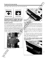
To install the secondary disconnects:
1 .) Engage Secondary Disconnect molded tabs i nto factory
formed slots as ind icated.
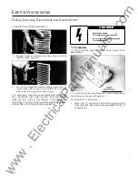
2.) Prior to final installation of the secondary d isconnect, it is
recommended that a drop of LocTite #271 be put on the
8-32 x 5/1 6-inch long counter-sunk screws.
The secondary disconnects are referenced as left top
(LT), left bottom (LB), right top (RT), and right bottom
(RB). Left and right are with respect to the user facing
the breaker. The recommended terminal points for acces
sories added in the field are illustrated below.
66
"T" Connectors
A
DANGER
Hazardous Voltage.
Will cause severe injury or death.
Do not attempt to install accessories
with voltage present.
"T"
connectors are used to connect power buses to the
SB breakers.
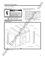
"T" connectors with mounting hardware ( 1 connector and appro
priate hardware shipped with each kit)
To install the
"T"
connectors:
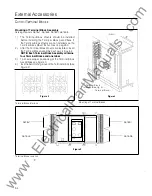
1 .
Mount the
"T"
connectors to the terminal pads with the
mounting bolts. Use torque value supplied with the "T"
connector kit.
www
. ElectricalPartManuals
. com


