Internal Accessories
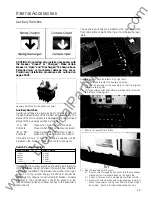
Auxil iary Switches
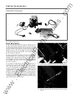
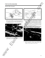
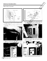
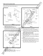
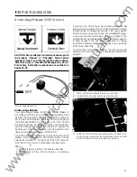
5.) Secure the trip unit in place with the reta·1n.1ng screw located
at the top of the trip unit Torque to 6-8 in. lbs. If trip unit
top is not secured properly, the interlock will prohibit clos
ing of the breaker.
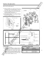
6.) Replace the front cover of the breaker, being careful not to
pinch wire leads routed to secondary disconnects or termi
nal blocks. Secure with eight (8) Phillips head screws.
Installation of the auxiliary switch is complete.
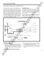
<RT1 >
Aux. 4 A
------'? • >--·
<RT2>
1 Aux. 4 A
�----
� � �----
Auxiliary Switch 4
<RT3>
1 Aux. 4 B
<RT 4>
:
>--
Auxiliary Sw1tch 5
:
<RT7>
1 Aux. 5 8
Note ���ii;:�lf¥i\t��r�l�����i�
r--- -
Aiarm Switch, Or Local Load
��---
Monitor Relay Is Installed.
Auxiliary Switch 6
1
<RT9>
<RT10� 1
<RT� :
<RT12>
<RB1 >
I
Auxiliary Switch 1
<R82>
I
-----'? I
-
�
��-------
. -
<R83>
I
- � 1
1
<R84>
<R85>
-7
Auxiliary
<R88>
I
I
<R89>
•
I
Auxiliary Switch 3
1
<R81 1 >
<R812>
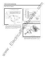
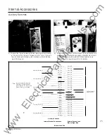
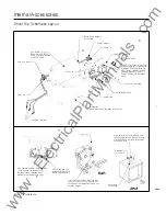
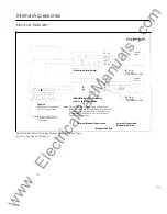
Auxiliary Switches
Internal Breaker Connections
_ _ _ _ _ _ _ _ _ _ _ _ _ _ _ _ _
!
Breaker Load End
Aux. 6 A
Aux. 6 A
Aux. 6 B
Aux. 6 8
Aux.
1
A
Aux. 1 A
Aux. 1 8
Aux. 1 8
Aux. 2 A
Aux. 2 A
Aux. 2 8
Aux. 2 8
Aux. 3 A
Aux. 3 A
Aux. 3 8
Aux. 3 8
External Connections
Breaker Right Side
Wiring Information
50
To Customer's
Applications
www
. ElectricalPartManuals
. com


