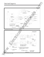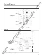
Electrical Diagrams
I
Control
Power
I
I_
<LT2> Remote Close
+
.NO! /
NC
COM
Local
Electric
Local Electric Close
AvAtldble As Factory Installed Opt10� Only
L
E
C
(Local
Electrtc 1
Close)
Switch
r ,
1 1 �
Sw
i
tc
h
(Handle Check)
HC
I
� ---+
Note·
Customer
1
May Provtde
Permissive Control
Through Thts Ltne
,L
No
' I
<HC-LCo-
L
<
<
L
T1> Elec. Oper
+
3�:�0
c7
l
(Latch Check)
:
<LT2> Rem Close +
1 1
J1-8
--
LC
.
--
<
--
-
- -
J1
7
/
<JI -?>
__
_
Swttch
-< f----
<LT3>_
Clo
�
e
+ __
,
Motor
Jl�6
<J1_(3>_
(Cam Check)
Controller
J
1
-
5
) )
<Ji-S>
--
CAM
<LT4>
S
pr
i
n
g
Ch l
nd
Jl-4
�
>
<J1___i:::_
__
_
I
I
Supplted
by
Customer
----<
'
<--
�LTS;:-;;MMc=;;;-
-=- 1'
J1-3
) >----'
<J1-3>
NO
----< :
(
-- -
--
J1-2
tJ'______:sl1
2> -
<>-
1
Swttch
) >-
(Sprrng
Check)
10
W Max
0.5
Amps Max
200
Vdc Max
' -�
<
I
Factory Installed Jumper
Wrre
:
,
,
Note. Customer
May Prevent
1
< L B I > ECI
I
Electric Closing Of The
Breaker
11
By
Replacing
Factory
Installed
J
u
mpe
r W1re W1th
A
Set
Of
External
Contacts
Electric Close
Interlock Option
--,
-
'.·1
-This W1re Is Not
1
Used When ECI
Is Installed
,;.;,able �s F,_io·f l�olaled Ouu·l (;rly
External Connections
Internal Breaker Connections
,v,Jl:j_
SC
I_
Fuse
1-3/4 A
Slo-Bio
Electric Operator
Motor Operator Wiring Diagram
I
I
I
I
I
I
I .
I I
Trip Unit
See Sheet
6
For All
Other
Trip Unit Connections
Note Trip Unit Plug Shown
As Viewed From Front
Of
Breaker
Bell Alarm/Display Module Relay
84
Note·
(SBDMR) Display Module Relay
Local Load Monitor Relay
Electronic Alarm Switch, Local Load Monitor
1
Relay, And Remote Indicator Panel Are Mutually 1
Exclusive. No Combination
Of
These Dev1ces
Is Permitted. See Sheet
6
For Connect1on
Of
Remote I ndicator Panel
Internal Breaker Connections
Breaker Load End
Alarm Reset Switch
Customer Supplied
Control
Power
1 .25A Max
1 50Vdc/200Vac Max.
External Connections
Breaker Right Side
www
. ElectricalPartManuals
. com

