Frame Installation Instructions
Moveable Drawout Element and Fixed-Mounted SB Breakers
To properly engage the moveable drawout element with
the racking mechanism, the crank pins on the sides of the
moveable drawout element must be i n the "unlocked"
position as illustrated and the interlock lever in the "up"
position. During shipping and handling the crank pins may
have rotated out of position. If so, rotate them to the pro
per position. The moveable drawout element may now
be moved/racked into the stationary drawout element.
Racking instructions are located in the Operating Instruc
tions section .
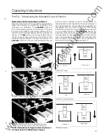
Crank Pin in Unlocked position.
Crank Pin in Test position.
C\0.1\K
����\D. Closed
01
Co\\1\ected
position.
Interlock Lever mechanism
Installing Fixed-Mounted SB Breakers
Prepare the switchboard for installation of the SB breaker in
accordance with the outline drawings at the end of this
section . The outline drawing for the 4000A frame is located
on pages 74-79. The locat ions of the mounting holes and
the recommended screws are depicted on the drawing .
All eight mounting screws will be used t o secure the
breaker to the switchboard .
Carefully uncrate the breaker and remove all packing
material . The keys for a breaker with a key interlock
accessory will be taped to the top of the breaker. If the
breaker is secured to a pallet, remove the securing device.
Lifting straps should go between the stabs.
Attach the lifting straps as i llustrated . The breaker should
not be lifted by the primary stabs; the lifting straps should
go
between the stabs. In this arrangement the breaker may
be
easily balanced while it is being lifted by a crane or
ho1st.
Lift the breaker into position and secure it with
all eight
mounting screws torqued to 15 ft . lbs. max. Remove
the
lifting straps.
II
www
. ElectricalPartManuals
. com


