Installation
110/293
Revision 11 • INSTALLATION AND OPERATING INSTRUCTIONS • NXPLUS C • 802-9081.9
➭ Remove the cable compartment cover and the front cover.
➭ Insert the panel connecting bolts M8x20 provided at the 4 fixing lugs ② of the right-hand
panel through the switchgear frame and bolt together with the left-hand panel (tightening
torque: 30 Nm).
➭ Check whether the bolted panels are in vertical position.
➭ Move each additional panel into position and align with the installed panels. Bolt the
alignment brackets and the frames together.
15.2
Fastening the panel to the foundation
The panel must be bolted together with the foundation rails at the fixing points in the base
frame.
➭ Bolt each panel diagonally to the foundation at 2 fixing points at least, see page 85, "Floor
openings and fixing points".
Use at least 2 fixing bolts M8 or M10 (tightening torque M8: 30 Nm, M10: 60 Nm).
➭
Resistance against shock, vibration and earthquakes:
Install additional floor bracings in
every panel, see page 87, "Resistance against shock, vibration and earthquakes (option)".
Bolt each panel to the foundation at 4 fixing points.
Use 4 fixing bolts M8 or M10 (tightening torque M8: 30 Nm, M10: 60 Nm).
15.3
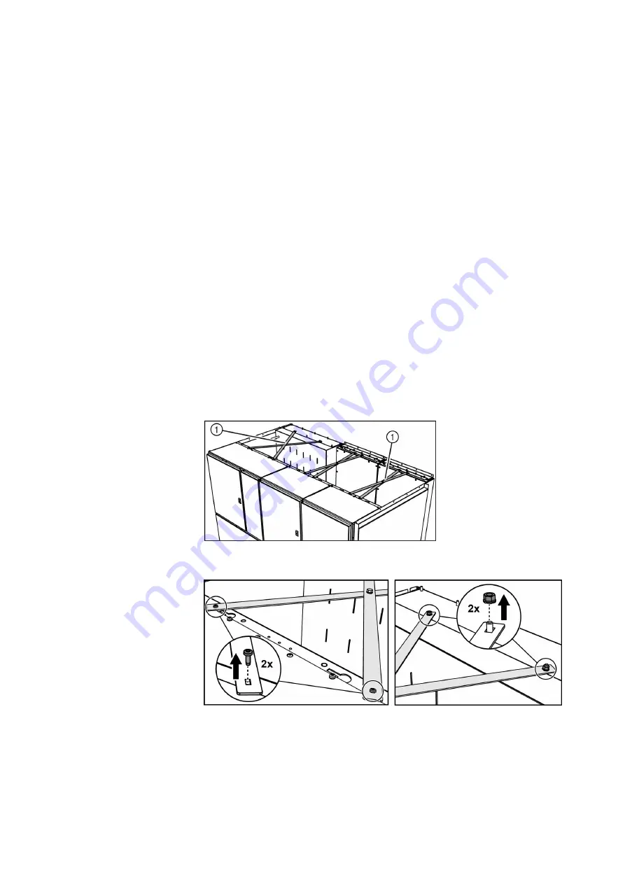
Removing transport braces
To assure the stability of the switchgear during transport, all panels with a pre-assembled low-
voltage compartment are equipped with transport braces. To install the switchgear, the
transport braces must be removed.
➭ Remove the nuts and bolts of the transport braces.
➭ Remove the transport braces.
✔ The transport braces are removed.
①
Transport braces


