Description
54/293
Revision 11 • INSTALLATION AND OPERATING INSTRUCTIONS • NXPLUS C • 802-9081.9
Fig. 29:
Coding of cable compartment cover for 600 mm panel with fuses (view from above)
9.13
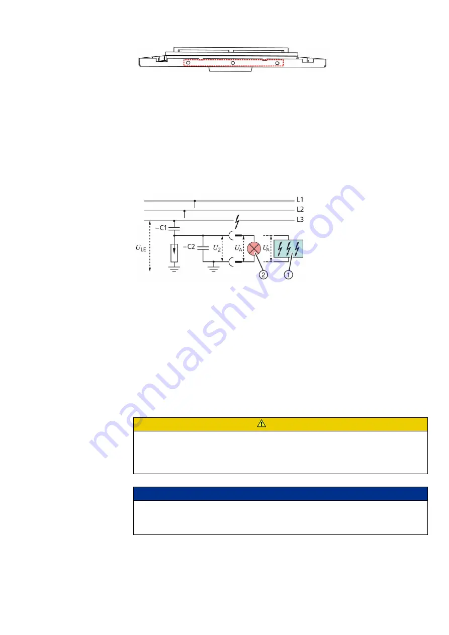
Voltage detecting systems
For voltage detection according to IEC 61243-5 and VDE 0682 Part 415 with the following
voltage detecting systems:
• Plug-in LRM voltage indicator
• Integrated voltage indicators:
- VOIS
- CAPDIS
- WEGA
• -C1: Capacitance integrated into bushing
• -C2: Capacitance of the connection leads and the voltage indicator to earth
• U
LE
= U
N
/ √ 3 during rated operation in the three-phase system
• U
2
= U
A
= Voltage at the interface (plug-in sockets) of the plug-in voltage indicator or the
test socket of the integrated voltage indicator
9.14
Accessories
Standard accessories
The standard accessories are located in the service flap in the switchgear termination.
• The label "Service flap equipment" shows the arrangement of the accessories inside the
service flap.
Fig. 30:
Voltage detecting system via capacitive voltage
divider (principle)
①
Integrated voltage indicator
②
Plug-in LRM voltage indicator
CAUTION
Risk of injury when closing the service flap
Fingers can be trapped between service flap and switchgear front.
➭ Hold service flap at the provided handle when closing it, and close it in a controlled
manner.
NOTICE
Service flap slamming closed
Can damage the switchgear.
➭ Hold service flap at the provided handle, and close it in a controlled manner.


