Installation
104/293
Revision 11 • INSTALLATION AND OPERATING INSTRUCTIONS • NXPLUS C • 802-9081.9
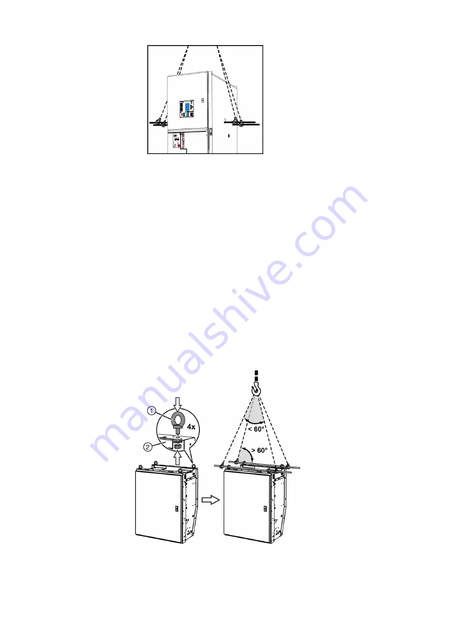
Fig. 59:
Craning the end panel (schematic representation)
➭ After craning, close the openings again. Undo the Torx bolts again and push them back to
the initial position. Tighten the Torx bolts.
Installing the transport
units
You may only start installing the transport units when
• all transport damages have been repaired
• the base frame has been levelled (1 mm/m), see DIN 43661
• the SF
6
gas filling in the vessels has been checked (see page 105, "Checking the ready-for-
service indicator").
• the accessories and the required material are complete (see page 96, "Before installation").
➭ Place the first (i.e. rearmost) transport unit as exactly as possible on its final location and
place the second one close to it, keeping a small distance so that the units can still be
aligned before bolting together.
➭ Remove packing and transport materials from the place of installation.
➭ Remove any dirt occurred during transport, as extreme cleanliness is required during
installation.
✔ Now the transport units are in the correct order for assembly.
Craning the low-voltage
compartment
➭ Mount four ring eyes with washers and hexagon nuts at the low-voltage compartment.
➭ Insert lifting rods through the ring eyes (diameter of lifting rods: 20 mm).
➭ Mount the lifting gear.
✔ Now the low-voltage compartment can be lifted onto the panel.
Fig. 60:
Craning the low-voltage compartment
①
Ring eye with hexagon nut
and washer
②
Low-voltage compartment


