background image

Installation 

UMSITRPDS3-1 


November 

2010 

4-24 


Models 7MF4333, 7MF4433, and 7MF4533 

920-07012-XXX-1.pdf 


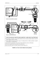
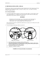
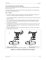
FIGURE 4-13  Differential Construction, Position Options 

4.4.2  Direct Mounting to Process, Model 7MF4433 or 7MF4533 

A differential transmitter can be interfaced to the process through a 
two- or three-valve manifold and supported by the piping 
connections (3-inch nipples) if mounted directly at the point of 
measurement. 
 
Transmitter process connections are on 2.13-inch (54 mm) centers 
to allow direct mounting (bolting) to a manifold with the same 
spacing. Each transmitter process connection (end cap) has two 
tapped 7/16-20 mounting holes and a 1/4 NPT tapped pressure 
inlet. High pressure (+) and low pressure (-) sides of the transmitter 
are marked by labels (see Figure 4-12) and engraved on the capsule 
between the end caps. 
 
Process orifice flanges with standard 2.13-inch spacing permit a transmitter and two- or three-valve 
manifold combination to be direct mounted. 
 
The procedure for mounting a transmitter to a two- or three-valve manifold, and the manifold to the 
orifice flanges, is covered by the installation instructions supplied by the manifold manufacturer. 
The following is a guide and may need to be modified for some installations. Teflon

®

 tape is the 

recommended thread sealant for process connections at the transmitter. 

1.


If installed, remove process connection blocks from the transmitter’s end caps (process manifold). 

2.


Press the supplied O-ring seals into the grooves in the face of the two- or three-valve manifold and 
bolt the transmitter end caps to the transmitter side of the two- or three-valve manifold. Tighten 
mounting bolts to 400 in/lbs (45.2 Nm). 

M

G

00352b

Nipple Mount for

Liquid Service

3-Valve
Manifold

High
Pressure
Side

Low
Pressure
Side

Flow

Orifice
Flanges

End Cap

Summary of Contents for 7MF4033 series

Page 1: ...ER S MANUAL Siemens Industry Inc UMSITRPDS3 1 Rev 10 November 2010 Supersedes Rev 9 SITRANS P Series DSIII Transmitters for Pressure Differential Pressure Flanged Level and Absolute Pressure Model 7MF4 33 ...

Page 2: ... the communicator nameplate for hazardous area certifications and approvals and other important information APPLICATION AND MODEL QUICK LOCATOR The following table provides an overview of measurement categories and available models For details pertaining to a particular model see the appropriate section for a dimension drawing the model designation table and specifications in Section 9 Model Desig...

Page 3: ... Alphanumeric and Shift Keys 2 7 2 4 GETTING TO KNOW THE COMMUNICATOR 2 8 2 4 1 Display Icons 2 8 2 4 2 Menu Structure 2 9 2 4 3 Reviewing Installed Devices 2 9 2 5 MAIN MENU 2 11 2 5 1 Offline Menu 2 12 2 5 2 Online Menu 2 18 2 5 3 Frequency Device Menu 2 21 2 5 4 Utility Menu 2 21 2 6 USING THE QUICK ACCESS KEY 2 23 2 6 1 Adding Quick Access Key Options 2 24 2 6 2 Deleting Quick Access Key Optio...

Page 4: ...LLATION TEST 5 1 5 1 TEST EQUIPMENT 5 1 5 2 INSTALLATION REVIEW 5 1 5 3 EQUIPMENT CONNECTION 5 2 5 4 VERIFICATION 5 3 5 4 1 Communication Test 5 3 5 4 2 Transmitter Selftest 5 3 5 4 3 Loop Test 5 4 5 5 TRANSMITTER ZERO AND SHUTOFF VALVE MANIPULATION 5 5 5 5 1 Absolute Pressure 5 5 5 5 2 Differential Pressure and Flow 5 8 5 5 3 Measuring Vapor 5 11 6 0 ON LINE CONFIGURATION AND OPERATION 6 1 6 1 LO...

Page 5: ...29 6 4 17 Device Information 6 30 6 4 18 Flow Measurement Differential Pressure 6 30 6 4 19 Diagnostic Functions 6 30 6 4 20 Simulation 6 33 6 4 21 Self Test and Master Reset 6 34 7 0 CALIBRATION AND MAINTENANCE 7 1 7 1 CALIBRATION 7 2 7 2 PREVENTIVE MAINTENANCE 7 3 7 2 1 Transmitter Exterior Inspection 7 3 7 2 2 Transmitter Exterior Cleaning 7 3 7 2 3 Transmitter Enclosure Interior Inspection 7 4...

Page 6: ...LATION EXAMPLE 13 2 13 3 SUPPRESSION CALCULATION EXAMPLE 13 2 13 4 RECOMMENDED METHOD 13 3 Online Configuration Map with Model 275 Communicator Online Configuration Map with Model 375 Communicator LIST OF FIGURES Figure and Title Page 1 1 Gauge Construction Pressure and Absolute Pressure Models 1 3 1 2 Differential Construction Differential Flow and Absolute Models 1 4 1 3 Differential Pressure an...

Page 7: ...Root Characteristic 6 15 6 3 Displayable Engineering Units 6 17 6 4 Sensor Trim 6 27 6 5 Pressure Min Max Pointer Example 6 32 6 6 Saturation Monitoring Examples 6 33 6 7 Simulation Circuit Diagram 6 34 7 1 Transmitter Exploded View 7 9 7 2 Display Assembly Installed and Partially Removed 7 11 7 3 Electronics Module Removal and Installation 7 12 7 4 Measuring Cell Alignment and Insertion Depth 7 1...

Page 8: ... Model 7MF4233 Specifications 9 10 9 5 Model 7MF4333 Model Designation 9 13 9 6 Model 7MF4333 Specifications 9 15 9 7 Model 7MF4433 Model Designation 9 18 9 8 Model 7MF4533 Model Designation 9 20 9 9 Models 7MF4433 and 7MF4533 Specifications 9 22 9 10 Models 7MF4633 and 7MF4812 Model Designation 9 25 9 11 Models 7MF4633 and 7MF4812 Specifications 9 28 9 12 Measuring Cells for Pressure Service Part...

Page 9: ...s a registered trademark of E I du Pont de Nemours and Company Hastelloy is a registered trademark of Haynes International Monel is a registered trademark of Special Metals Corporation HART is a registered trademark of the HART Communication Foundation All product designations may be trademarks or product names of Siemens Industry Inc or other supplier companies whose use by third parties for thei...

Page 10: ... that should be read before proceeding Electrical shock hazard Either symbol indicates the presence of an electrical shock hazard The associated text states the nature of the hazard what can happen as a result of the hazard and how to avoid the hazard Explosion hazard Symbol indicates that the danger of an explosion hazard exists The associated text states the nature of the hazard what can happen ...

Page 11: ...be downloaded from the Siemens Internet site see the Customer Product Support section of this manual for the address For the purpose of this manual and product labels a qualified person is one who is familiar with the installation assembly commissioning and operation of the product and who has the appropriate qualifications for their activities such as Training instruction or authorization to oper...

Page 12: ...he symbol at right appears on a circuit board or other electronic assembly to indicate that special handling precautions are needed A properly grounded conductive wrist or heel strap must be worn whenever an electronics module or circuit board is handled or touched Static control kits are available from most electrical and electronic supply companies Electronic assemblies must be stored in static ...

Page 13: ... a bench test of the transmitter to ensure proper operation of all transmitter functions Start up configuration is described here Section 4 Installation furnishes specific information for mechanical and electrical installation of the transmitter Section 5 Post Installation Test describes how to confirm that the transmitter has been installed correctly sometimes referred to as commissioning Section...

Page 14: ... a digital signal for the microcontroller The microcontroller modifies and corrects the signal for linearity and temperature and a digital to analog converter produces a 4 20 milliampere output signal for the loop The transmitter can be installed quickly and easily using one of the optional mounting brackets Illustrations showing mounting hardware and dimensions are provided in this manual Measuri...

Page 15: ...Electronics module and display remove enclosure cap for access 6 7 8 9 10 11 12 13 Hinged access cover over magnetic pushbuttons Mounting bracket optional Tag plate Approval plate Rating plate on other side Enclosure ground screw Enclosure setscrew Enclosure rotation limits Enclosure rotation reference arrow see Section 4 for details This Figure is for Models 7MF4033 and 7MF4233 FIGURE 1 1 Gauge C...

Page 16: ...ccess Hinged access cover over magnetic pushbuttons Sealing screw with vent shown optional Side vent for measuring liquid 10 11 12 13 14 15 16 17 Side vent for measuring gas supplement H02 Mounting bracket optional Enclosure setscrew Enclosure rotation limits see 14 reference arrow Enclosure rotation reference arrow see Section 4 for details Tag plate Approval plate Rating plate on other side Encl...

Page 17: ...ing screw Enclosure setscrew Enclosure rotation limits enclosure rotation reference arrow on neck see Section 4 for details 10 11 12 13 14 15 Blanking plug Access cover over magnetic pushbuttons Electrical connection M20 x 1 5 1 2 14NPT Tag plate Approval plate Rating plate on other side Enclosure ground screw This Figure is for Models 7MF4433 and 7MF4533 with H03 option FIGURE 1 3 Differential Pr...

Page 18: ...cap for access Electronics module and display remove enclosure cap for access 7 8 9 10 11 12 13 Access cover to magnetic pushbuttons Sealing screw with vent shown optional Enclosure setscrew Enclosure rotation limits Enclosure rotation reference arrow not shown see Section 4 for details Tag plate Rating plate approval plate on other side This Figure is for Models 7MF4633 and 7MF4812 FIGURE 1 4 Fla...

Page 19: ...n be parallel connected to a Multi Drop network using only shielded twisted pair cable The HART protocol provides communication between the transmitters and a HART compatible controller recorder or other device Each transmitter is identified by a unique network address that is selected during configuration Display Magnetic Pushbuttons and Loop Connections The optional display Figure 1 6A permits l...

Page 20: ...ton access cover Enclosure cap 1 2 3 4 Field terminals for analog output Analog output test terminals Enclosure ground Electrical entrances plug unused entrance A Digital Display B Field Terminals FIGURE 1 6 Digital Display and Field Terminals Transmitters have an intrinsically safe explosion proof NEMA 4x IP67 68 field mountable hardened enclosure Electrical conduit connections are 1 2 14 NPT or ...

Page 21: ...MENS Springhouse PA USA SITRANS P XP DIP or IS CL I ZN 0 1 AEx ia IIC T4 T6 FM Ex ia IIC T4 T6 CSA cert 2000 1153651 CL I DIV 1 GP ABCD T4 T6 CL II DIV 1 GP EFG CL III Vi 30V Ii 100 mA Pi 0 75 W Ci 6 nF Li 0 4 mH Vmax 30 V Ta T4 40 85ºC T6 40 60ºC ENCL Type 4X seal not required FW 0011 03 06 HW 02 05 01 FM APPROVED MG00384b Per Control Dwg A5E00072770A CL 1 Div 2 GP ABCD T4 T6 CL II DIV 2 GP FG CL...

Page 22: ...lic Internet site see the table has current revisions of technical literature in Portable Document Format for downloading To send an instrument to Siemens for warranty or non warranty service call Customer Service and Return to request a Return Material Authorization RMA see the table below IMPORTANT An instrument must be thoroughly cleaned decontaminated to remove any process materials hazardous ...

Page 23: ...and non hazardous locations WARNING Explosion can cause death or serious injury Before connecting the HART Communicator in an explosive atmosphere be sure that the instruments in the loop are installed in accordance with intrinsically safe or non incendive field wiring practices Refer to the Communicator nameplate and the supplied manual for certifications and approvals before connecting or making...

Page 24: ...arrow Down Arrow Select Forward right arrow Alphanumeric Keys keypad number sequence may be different from that shown Shift Keys Use to select alphabetic and other characters above a number period or dash Communicator Nameplate On back of device See nameplate for certifications and approvals before connecting in a hazardous location Communicator model number and serial number on back Connection pa...

Page 25: ...ation Connect as shown above Hazardous location Refer to Communicator nameplate and the manual supplied with the Communicator for certifications and approvals before connecting The HART Communicator is a non polar device 2 The System Power Supply may be part of the host input device or a separate device 3 Network resistance equals the sum of the barrier resistances and the current sense resistor M...

Page 26: ... bottom line of each menu is reserved for dynamic labels for the software defined function keys F1 F4 which are found directly below the display More information on software defined function keys is given in the next section 2 3 2 Software Defined Function Keys The four software defined function keys softkeys located below the LCD and marked F1 through F4 are used to perform software functions as ...

Page 27: ...er to yes no question PGUP Move up one help screen PGDN Move down one help screen NO Answer to yes no question ALL Include current Quick Access Key item on Quick Access Key menu for all devices PREV Go to previous message in a list of messages NEXT Go to next message in a list of messages ONE Include Quick Access Key item for one device NEXT Go to the next variable in off line edit SAVE Save infor...

Page 28: ...and numeric data DOWN ARROW KEY Use to move the cursor through a menu or a list of options or to scroll through lists of available characters when editing fields that accept alpha and numeric data LEFT ARROW PREVIOUS MENU KEY Use to move the cursor to the left or back to the previous menu RIGHT ARROW SELECT KEY Use to move the cursor to the right or to select a menu option QUICK ACCESS KEY HOT KEY...

Page 29: ...ds to the desired menu option For example to quickly access the Utility menu from the Main menu simply press 4 on the keypad 2 3 4 2 Data Entry Some menus require data entry Use the alphanumeric and shift keys to enter all alphanumeric information into the HART Communicator Pressing an alphanumeric key alone while editing causes the large character in the center of the key number 0 9 decimal point...

Page 30: ...r not connected Main menu off line operation Communicator connected Online menu on line operation To work off line when connected to a powered loop access the Main menu from the Online menu by pressing the LEFT ARROW PREVIOUS MENU key Note Communicator internal operation is controlled by firmware Consequently operation will depend upon the firmware version and the installed device drivers as discu...

Page 31: ...contrast 5 Press ESC F3 to return to the Configure Communicator menu 6 Press the LEFT ARROW PREVIOUS MENU key two times to return to the Main menu 7 Press the ON OFF key to turn the Communicator off 2 4 3 Reviewing Installed Devices For the HART Communicator to recognize a specific HART compatible device it must contain a description for that device Communicator device descriptions for Moore and S...

Page 32: ...340__B 340S Dev V1 DD V1 340 Transmitter 341 Type 5 Dev V1 DD V1 341 Transmitter 8 94 Present Model s 341 343 Dev V1 DD V1 343 Temperature Transmitter 344 Dev V1 DD V1 344 Transmitter Controller 8 90 8 94 Model s 344 Dev V2 DD V1 344 Transmitter Controller 8 90 Present Model s 344 345 Dev V1 DD V1 345 Transmitter Controller 8 99 Present Siemens Menu SITRANS P DS3 Dev V2 DD V1 Siemens DS3 Pressure ...

Page 33: ... powered HART device Press the Communicator s ON OFF key the Online menu appears To access the Main menu press the LEFT ARROW PREVIOUS MENU key until the Main menu appears Alternatively press HOME F3 to display the Online menu followed by the LEFT ARROW PREVIOUS MENU key to display the Main menu In the Main menu access an additional menu by either Moving the cursor to the selection using the UP or...

Page 34: ...ta type 4 Print 5 Delete 6 Rename 7 Compare 2 Online 3 Frequency Device Note See Table 2 3 for additional menu options 4 Utility FIGURE 2 4 Offline Menu Map TABLE 2 3 Offline Menu Map Continued Edit individually Options1 Tag type 2 Alarm URV type Flange type select Extension length select Descriptor type Pres xfer function select Flange material select Electrical connection select Date type Pressu...

Page 35: ...The Field Device Revision menu contains the currently installed software revisions for the field device and device descriptions DD for the model selected from the Model menu Select the software revision RIGHT ARROW SELECT or number to access the Blank Template menu at right To display the software revision for a particular device connect the Communicator to the device and follow instructions given...

Page 36: ...ns and contains the operating system software and device application software in non volatile memory The Data Pack stores up to 100 typical configurations in nonvolatile removable memory Example From the Offline menu choose 1 New configuration This displays the Manufacturer menu Choose a device then choose a model from the Model menu Choose a software revision from the Fld dev rev menu The Communi...

Page 37: ...the RIGHT ARROW SELECT key to display the Data Type menu below right Data Type Standard refers to all user editable variables in a device configuration Data Type Partial refers to only the marked editable variables Data Type Full refers to a all device variables whether user editable or not In general it is best to save as Data Type Standard Saving as Data Type Full preserves a complete configurat...

Page 38: ...is particularly valuable for the Data Pack which stores up to 100 configurations Sort allows unique device configurations to be grouped and displayed by Tag Descriptor or user assigned Name Use Filter to group and display configurations according to certain characters within the chosen device identifier Tag Descriptor or Name Filter is useful for selecting all the tags from a certain area of the p...

Page 39: ...ard configuration then saved prior to editing Copy To specifies the storage location for a copy of the configuration Copy To also provides a way to change the configuration name Send sends a saved configuration to a connected device Print not implemented with firmware release 1 6 Delete removes a saved configuration from memory A confirmation message appears Press Yes or No to complete the functio...

Page 40: ...Generic Menu The Generic Online menu at right is the first menu in the generic interface It displays critical up to date device information Configuration parameters for the connected device may be accessed using the Device setup option Figure 2 6 shows the complete Generic Online menu tree From the Online menu use the options below to change device configurations Device setup provides access to th...

Page 41: ...led setup 1 Sensors 1 Pressure sensor 1 Pressure 2 Unit 2 Temperature sensor 1 Sensor temperature 2 El temperature 2 Signal condition 1 Process variables 2 Position correction 3 Zero span set 4 Damping 5 Transfer function 6 Measuring speed 3 Output condition 1 Analog output 2 HART output Polling address and number of preambs 4 Device information 1 Ranges and limits Module range pressure USL and LS...

Page 42: ...er function 6 Damping 4 Detailed setup 1 Sensors 1 Process variables 2 Sensor service 1 Sensor trim 2 Characterize 3 Unit 2 Signal condition 1 Process variables 2 Range values 3 Unit 4 Transfer Function 5 Damping 3 Output condition 1 Process variables 1 Loop test 2 D A trim 3 Scaled D A trim 2 Analog output 3 AO alarm type 4 HART output 1 Poll address 2 Number of request preams 3 Burst mode 4 Burs...

Page 43: ...w right Use this menu to set the polling adjust the contrast of the LCD set the Communicator shutoff time or set how many diagnostics messages to ignore before a warning message is displayed Use the Polling option to direct the HART Communicator to search for a connected device The Communicator finds every device in the loop and lists them by tag number If Polling is Never Poll then the Communicat...

Page 44: ...ytes The PC selection is not implemented in firmware release 1 6 2 5 4 5 Simulation The HART Communicator provides a mode that allows users to simulate an on line connection to a HART compatible device without connecting to the device The simulation mode is a training tool that allows users to become familiar with different devices before configuring them in a critical environment Simulation of an...

Page 45: ...Section 6 1 3 More options can be added to provide rapid access to frequently performed tasks User defined options can be deleted later but the factory option is permanent To use the Quick Access Key 1 Connect the Communicator to a powered HART compatible device 2 Press the Quick Access Key upper right hand key in the action keys group The Communicator will power up and display the Quick Access Ke...

Page 46: ...was displayed when Shift Quick Access Key was pressed 4 After pressing ADD F3 either press ALL F1 to add the new option to the Quick Access Key menu for all the HART compatible devices supported by the Communicator or press ONE F4 to add the option to the Quick Access Key Menu only for the type of device that is currently connected 5 Next the question Mark as read only variable on Quick Access Key...

Page 47: ...n press the Quick Access Key 2 The Hotkey Configuration menu displays at right 3 Using the UP or DOWN arrow key move the menu bar to highlight the option to be deleted and press DEL F2 Factory provided options cannot be deleted 4 When finished deleting options press EXIT F4 to exit the Hotkey Configuration menu and return to the menu of the last option deleted SITRANS P Hotkey Configuration ADD De...

Page 48: ...Model 275 Universal Hart Communicator UMSITRPDS3 1 November 2010 2 26 ...

Page 49: ...performed and configuration procedures can be practiced To operate the transmitter on a test bench make the connections shown in Figure 3 1 Figure 3 2 shows the connections if these tests are to be performed after transmitter installation A pressure source can also be connected _ 4 20 mA _ I O MG00357a _ 250 mA Vdc 1 2 3 4 5 1 Transmitter field terminals 2 Analog output test terminals 3 Digital mi...

Page 50: ...Connections 3 1 1 Test Equipment TEST EQUIPMENT DESCRIPTION see Specifications Section 9 3 Power Supply 10 5 to 45 Vdc see Power Supply Requirements Section 4 3 5 Multimeter Current Range 4 to 20 mA to measure loop current Voltage Range 0 50 Vdc to measure power supply and loop voltage Current Sense Resistor 250 to 1100Ω to support HART digital communications Configuration Device Model 275 HART Co...

Page 51: ...RT Communicator has been established 1 In the Online menu choose option 3 Device setup then press 2 Diag Service and finally press 2 Simulation Test 2 In the Simulation Test menu choose option 2 Test and then press1 Self test or press the RIGHT ARROW SELECT key to start the test 3 The transmitter performs the self test If testing is successful the message Self test OK appears and the Communicator ...

Page 52: ...figuration to the transmitter If the configuration is incompatible with the transmitter a warning message will appear 3 5 CHECKING TRANSMITTER OUTPUT To be sure that the transmitter is reading the proper pressure in the proper units use a dead weight tester or other acceptable pressure standard to apply 0 25 50 75 and 100 of input values to the transmitter Check that the corresponding outputs are ...

Page 53: ...or additional statements concerning installation in a hazardous environment 4 1 EQUIPMENT DELIVERY AND HANDLING Prior to shipment a transmitter is fully tested and inspected to ensure proper operation It is then packaged for shipment Most accessories are shipped separately The contents of a box are listed on a packing slip 4 1 1 Receipt of Shipment Each carton should be inspected at the time of de...

Page 54: ...ns that are needed to ensure successful mechanical and electrical installations 4 3 1 Mechanical Select the application Series DSIII transmitters are suitable for but not limited to Flow measurement Gauge pressure measurement Level measurement Draft pressure measurement Absolute pressure measurement High differential pressure measurement Hydrostatic tank gauging measurement Determine the physical ...

Page 55: ...r servicing or removal Gauge Construction Model Install a two valve manifold for similar purposes to those listed above Flange Model Consider using flushing rings to flush and clean the process connection without removing the flange Prepare installation site drawings showing the following Location of the Master Device e g HART Communicator or controller location and identification of each transmit...

Page 56: ...nsmitter Valves used in pressure service should be either globe or gate type Valves used in gas service should be of a type that does not permit condensate to build up behind the valve Install sediment chambers with drain valves to collect solids suspended in process liquids or moisture carried with non condensing gases Install air chambers with vent valves at high point in piping to vent gas entr...

Page 57: ...er Above Orifice Preferred for Gas Flow Flow High Pressure Side Low Pressure Side 3 Valve Manifold Vertical Main Line Flow Transmitter Below Orifice Flow 3 Valve Manifold High Pressure Side Low Pressure Side Vertical Main Line Flow Transmitter Above Orifice Flow Low Pressure Side 3 Valve Manifold High Pressure Side Model 7MF4433 or 7MF4533 Model 7MF4433 or 7MF4533 Model 7MF4433 or 7MF4533 FIGURE 4...

Page 58: ...e line senses pressure only The two pressures oppose each other canceling the effect of static pressure 4 Distance X can be any distance since both high and low pressure lines have equal and opposite forces which cancel the forces created by this distance 5 Entire length of low pressure pipe is kept full of condensate to act as a reference 6 See Appendix C for information on calculating suppressed...

Page 59: ...ety Shut Off Valve Liquid Shut Off Valve Union Sediment Chamber and Drain Valve Used to collect solids in liquid suspension or moisture carried with non condensing gas OR Elevated Zero Range Wet Gases Non Condensing and Liquids with Solids in Suspension Suppressed Zero Range Wet Gases Non Condensing and Liquids with Solids in Suspension Safety Shut Off Valve Gas Safety Shut Off Valve Liquid Union ...

Page 60: ...2010 4 8 MG00347a Safety Shut Off Valve Shut Off Valve Drain Valve Filling Tee with Hex Plug To Drain Model 7MF4033 or 7MF4233 Gauge Construction or Model 7MF4333 Differential Construction FIGURE 4 4 Steam Service Below the Line Mounting ...

Page 61: ...el Notes 1 Transmitter may be mounted at or below the minimum level to be measured 2 Open or vented vessels require only a high pressure HP connection 3 High pressure line senses static pressure plus level Low pressure line senses pressure only The two pressures oppose each other canceling the effect of static pressure 4 Distance X can be any distance since both high and low pressure lines have eq...

Page 62: ...or analog mode operation the following statements apply The transmitter outputs a 4 20 mA signal for input to devices such as controllers and recorders A Point to Point network is used comprising a transmitter Primary Secondary Master and other non signaling devices The transmitter polling address is 0 zero Point to Point networks are shown in Figures 4 6 4 7 and 4 8 The optional display can be us...

Page 63: ...s shown separate from the host input device In practice it may be part of the host input device This device can be a HART or non HART signaling device a Primary Master or a Secondary Master Network resistance equals the sum of the barrier resistances and the current sense resistor Minimum value is 250 Ohms maximum value is 1100 Ohms Connect the HART Communicator as shown in Figure 2 2 for hazardou...

Page 64: ...um value is 1100 Ohms 2 Connect the HART Communicator as shown in Figure 2 2 for hazardous and non hazardous locations The HART Communicator is a non polar device 3 Supply and return barriers are shown Interconnect all cable shields and ground only at the barriers 4 Procidia Model 353R or i pac terminal assignments are 34 Analog Input 1 35 Analog Input 1 Common 33 24 Vdc 18 Station Common 5 For ac...

Page 65: ...m value is 1100 Ohms 2 Connect the HART Communicator as shown in Figure 2 2 for hazardous and non hazardous locations The HART Communicator is a non polar device 3 Supply and return barriers are shown Interconnect all cable shields and ground only at the barriers 4 Procidia Model 353R or i pac terminal assignments are 34 Analog Input 1 35 Analog Input 1 Common 33 24 Vdc 18 Station Common 5 For acc...

Page 66: ...dress 4 3 5 Power Supply Requirements A power supply1 is needed to power the transmitter s The power supply can be A separate stand alone supply capable of powering several transmitters It can be mounted in a control room or in the field Follow the power supply manufacturer s recommendations with regard to mounting and environmental considerations Located in a controller such as a Primary Master o...

Page 67: ...a HART or non HART signaling device a Primary Master or a Secondary Master 2 Network resistance equals the sum of the barrier resistances and the current sense resistor Minimum value is 250 Ohms maximum value is 1100 Ohms 3 A maximum of 15 transmitters may be connected All must be configured for digital mode 4 Connect the HART Communicator as shown in Figure 2 2 for hazardous or non hazardous loca...

Page 68: ...inimum network power supply voltage requirement is a function of Network Resistance and full scale current 20 mA and is calculated by the following formula Minimum Power Supply Output Voltage 10 5 volts 0 02 Network Resistance in ohms Power supply output voltage must be greater than the calculated value The minimum voltage across the input terminals of a transmitter is 10 5 volts 2 Calculate the m...

Page 69: ...he calculated value The maximum voltage Vmax permitted across the input terminals of a transmitter is Non intrinsically safe transmitter 45 volts Intrinsically safe transmitter 30 volts The maximum number of transmitters that can be connected to a Multi Drop Network is 15 Each transmitter is parked in a low current draw mode 4 mA to conserve power Ensure that the network power supply is capable of...

Page 70: ...one conductor and the other conductor connected to the shield C may be in pF ft or pF meter Cf Total input terminal capacitance of field instruments the Primary Master is excluded Cf is given by the following formula Cf sum of all Cn values x 5000 Where Cn is an integer e g 1 2 3 corresponding to the input terminal capacitance of a Field Instrument Cn values are determined as follows FIELD INSTRUM...

Page 71: ...he power supply and transmitter A junction should be a simple electrical series connection containing NO repeaters or other devices active or passive that can degrade HART communications 4 3 8 Safety Barriers Installed safety barriers must comply with the following Locate intrinsic safety barriers between the system power supply e g Primary Master if used residing in the non hazardous area and the...

Page 72: ...to its function Miscellaneous hardware must be passive two terminal devices Miscellaneous hardware may not generate any type of noise or signals other than noise that is inherent in resistive components Individual miscellaneous hardware must meet the following requirements Capacitance to ground 50 pF maximum Resistance to ground 1 MΩ minimum Impedance if series connected Less than 10Ω Impedance if...

Page 73: ...he installation environment hazardous or non hazardous or by the requirements of a regulating agency The following grounding practices are field proven and will reduce magnetically coupled interference Select the appropriate option from the three bulleted items below for the installation at hand Hazardous location ground the shield s only at the barrier s or as recommended on the appropriate contr...

Page 74: ...l and Gauge Construction A differential or absolute transmitter can be mounted to a vertical or horizontal 2 inch pipe using an optional mounting bracket kit kit part numbers are given in Section 9 2 Accessories 1 Refer to the appropriate figure and determine orientation of bracket and transmitter on selected pipe 2 As shown in the appropriate figure fasten the transmitter to the mounting bracket ...

Page 75: ...nd 7MF4233 920 07010 XXX 1 pcx FIGURE 4 11 Pipe Mounting Gauge Construction MG00402a Low Pressure Side High Pressure Side Models 7MF4033 7MF4433 and 7MF4533 920 07011 XXX 1 pdf Labels Low and High Pressure Sides FIGURE 4 12 Pipe Mounting Differential Construction ...

Page 76: ...le between the end caps Process orifice flanges with standard 2 13 inch spacing permit a transmitter and two or three valve manifold combination to be direct mounted The procedure for mounting a transmitter to a two or three valve manifold and the manifold to the orifice flanges is covered by the installation instructions supplied by the manifold manufacturer The following is a guide and may need ...

Page 77: ...essel The flange mounted diaphragm is factory assembled to the high pressure side of the transmitter measuring cell Figure 9 5 shows a typical flanged level transmitter Table 4 2 includes the following mounting information Flange thickness Flange diameter and pressure rating Number of flange mounting holes Flange mounting hole diameter Flange bolt circle diameter Refer to Figure 9 5 and Table 4 2 ...

Page 78: ... 0 94 23 81 3 70 93 98 5 8 8 4 300 10 00 254 00 7 875 200 03 1 25 31 75 3 70 93 98 3 4 8 50MM 10 16 BAR 6 50 165 00 4 92 125 00 0 71 18 00 M16 4 50MM 25 40 BAR 6 50 165 00 4 92 125 00 0 79 20 00 M16 4 80MM 10 16 BAR 7 87 200 00 6 30 160 00 0 79 20 00 Consult Factory 0 12 3 00 M16 8 DIN 2526 80MM 25 40 BAR 7 87 200 00 6 30 160 00 0 94 24 00 M16 8 TYPE C 100MM 10 16 BAR 8 66 220 00 7 09 180 00 0 79 ...

Page 79: ... in the enclosure neck is rotated past the enclosure rotation arrow on the measuring cell damage to internal electrical connections can occur requiring replacement of the measuring cell After positioning the enclosure tighten the enclosure setscrew to between 30 1 in lbs and 31 9 in lbs 3 4 N m and 3 6 N m 2 Position the display as necessary Refer to Section 4 5 2 MG00353a Differential Constructio...

Page 80: ...crewdriver to remove the two screws holding the display The display is electrically connected to the transmitter electronics by the display cable Refer to Figure 4 15 5 Hold the display just in front of the transmitter enclosure and rotate it in quarter turns to find the viewing position where reading is easiest Four positions 90 apart are provided Do not rotate the display more than 180 in a cloc...

Page 81: ...for at least 105 C 221 F When routing conduit avoid areas that might subject the conduit to chemical or physical abuse or areas with high electromagnetic interference radio frequency interference EMI RFI conditions Install conduit for field wiring If a high humidity environment can exist and the transmitter is located at a low point in the conduit run install drain seals at the transmitter s condu...

Page 82: ...eed the maximum permitted pulling tension on the cables Maximum tension is normally specified as 40 of the cable s breaking strength Do not exceed the maximum conduit fill specified by the National Electric Code 4 5 3 3 Access to Transmitter Terminal Compartment 1 Remove the enclosure cap closest to the electrical entrance by turning it counterclockwise 2 Install the enclosure cap by turning it cl...

Page 83: ...minals 2 Access the transmitter signal terminals by removing the enclosure cap nearest to the electrical entrance Turn the cap counterclockwise 3 Determine method of connection to transmitter signal terminals see Figure 4 17 for typical connection methods 4 Strip loop cable and conductors Install ring tongue or spring spade terminals for 8 screws and the cable conductor gauge If terminals will not...

Page 84: ... ground such as a nearby metal cold water pipe 1 2 3 4 5 6 MG00355a 1 Solid conductor with loop formed in end of lead 2 Stranded conductor with spring spade terminal 3 Stranded conductor with ring tongue terminal 4 One of three terminals in the electrical enclosure Remove end cap to access terminals 5 Terminal screw 6 Pressure plate FIGURE 4 17 Network Conductor Terminations ...

Page 85: ...talling a transmitter in a hazardous area check the rating and approval plates on the transmitter and Section 9 Model Designation and Specifications for required approvals or certifications Explosion Proof Installation If the installation is required to be explosion proof as defined by the National Electrical Code refer to a current copy of the Code and the following User supplied explosion proof ...

Page 86: ...Installation UMSITRPDS3 1 November 2010 4 34 ...

Page 87: ...n proof rating is required remove power from the transmitter before removing either enclosure cap If a pre installation test of the transmitter was not performed review Section 3 Pre Installation Test as the described tests can be performed after installation 5 1 TEST EQUIPMENT User configuration data for the transmitter s HART Communicator see Section 2 of this manual Laboratory grade digital mul...

Page 88: ...ignal or power wiring that may cause interference 5 Check that a current sense resistor of the correct value has been installed 6 Apply power to the power supply or other loop power source e g controller Use the DMM to check power supply output voltage Note that the transmitter is on whenever power is applied 5 3 EQUIPMENT CONNECTION 1 Connect the equipment as shown in Section 4 Installation in th...

Page 89: ...er address 0 and transmitter model number Repair as necessary and repeat step 1 3 MULTI DROP NETWORK Press Yes F1 to enter digital mode and search for devices with polling addresses of 1 15 If the Communicator finds a transmitter on a Multi Drop Network the Online menu with the transmitter s type and tag name is displayed Each transmitter connected to the loop can be interrogated in sequence Go to...

Page 90: ...ght 4 Press 1 on the keypad or ENTER F4 to select the 4 mA option The Communicator displays the message Fld dev output is fixed at 4 000 mA Press OK F4 to confirm and proceed with testing or press ABORT F3 and proceed to step 8 5 Read the DMM The value should be 4 mA 6 Repeat steps 4 and 5 using the 20 mA output level The DMM reading should be 20 mA 7 For outputs other than 4 or 20 mA choose optio...

Page 91: ...angements may be advisable depending on the system configuration WARNING Improper operation of the valves can result in serious injury or considerable material damage Read and understand the complete procedure before starting a post installation test 5 5 1 Absolute Pressure Absolute pressure transmitters with gauge construction or with differential construction can be commissioned using the follow...

Page 92: ...ponding to zero 4 Check zero and correct if necessary 5 Close the test connection shutoff valve 2B 6 Open the shutoff valve 4 on the pressure tap 7 Open process shutoff valve 2A Transmitter above the pressure tapping point normal arrangement Transmitter below the pressure tapping point exception 1 2 3 Transmitter Shutoff fitting A Shutoff valve to the process B Shutoff valve for test connection or...

Page 93: ...ransmitter through the test connection shutoff fitting 2 a pressure corresponding to zero 4 Check zero and correct if necessary 5 Close shutoff valve 2B 6 Open shutoff valve 4 on the pressure tap 7 Open process shutoff valve 2A 1 Transmitter 2 Shutoff fitting A Shutoff valve to the process B Shutoff valve for test connection or venting screw 3 Pressure pipe 4 Shutoff valve 5 Drain valve 6 Condensa...

Page 94: ...wrongly or improperly In the case of hot process liquid or gas the individual operating steps must be performed in rapid succession Otherwise the valves and the transmitter may be over heated leading to damage 5 5 2 1 Measuring Gases Operate the shutoff valves in the following order Refer to Figure 5 4 to identify the valves used in the procedure 1 Close all valves 2 Open both shutoff valves 5 at ...

Page 95: ...valves used in the procedure 1 Close all valves 2 Open both shutoff valves 5 at the pressure taps 3 Perform one of the following depending upon transmitter location Transmitter below the active pressure tap Open both blowout valves 7 one after the other Transmitter above the active pressure tap Open both vent valves 8 slightly until air free liquid emerges 4 Close both blowout valves 7 or vent val...

Page 96: ... 3A by 1 2 turn 12 Check and correct zero 4 mA if necessary at zero bar 13 Close the compensation valve 2 14 Open the active pressure valves 3A and 3B fully Transmitter above the active pressure taps normal arrangement Transmitter below the active pressure taps exception 1 2 3 4 Transmitter Compensation valve Active pressure valves Active pressure lines 5 7 10 12 Shutoff valves Blowout valves Acti...

Page 97: ...n valve 2 3 Wait until the vapor in the active pressure lines 4 and in the compensation vessels 13 has condensed 4 Open the active pressure valve 3A and the vent valve at the high pressure chamber of the transmitter 1 slightly until air free condensate emerges 5 Close the vent valve 6 Open the vent valve at the low pressure chamber of the transmitter 1 slightly until air free condensate emerges 7 ...

Page 98: ...f necessary at zero bar 12 Close the compensation valve 2 13 Open the active pressure valves 3A and 3B fully This completes the post installation testing Disconnect test equipment connect any disconnected wires and restore any removed protective covers on the transmitter or other devices ...

Page 99: ...r that does not have a display Finally Section 6 4 provides the steps to configure and monitor a transmitter from a HART Communicator 6 1 LOCAL OPERATION AND DISPLAY Local configuration and operation make use of built in magnetic pushbuttons and an optional digital display As shown in the adjacent figure the display 1 is behind the enclosure cap The magnetic pushbuttons are under the hinged cover ...

Page 100: ...nt limit exceeded Mode 4 set damping Upper damping value exceeded Lower damping value exceeded Mode 5 set zero blind2 Upper sensor limit exceeded Lower sensor limit exceeded Mode 6 set full scale blind3 Upper sensor limit exceeded Lower sensor limit exceeded Mode 7 set zero position correction Maximum span exceeded by more than 5 Mode 12 set root switch point Square root switch point exceeded by m...

Page 101: ... in the Numeric display should a transmitter hardware or software problem occur A message describing the error will scroll horizontally through the unit bargraph display This information is also available at the HART Communicator 6 1 5 Output Signal Range The output signal is divided into defined areas The transmitter converts the measured pressure into an output current that is normally in the ra...

Page 102: ... default value Recommended setting range for lower fault current range and lower modulation range limit Recommended setting range for upper fault current range and upper modulation range limit 6 1 6 Mode Display An operating mode is selected by pressing the M pushbutton The selected mode is shown in the lower left quadrant of the digital display In the example at right mode 4 Electric Damping has ...

Page 103: ...essing the M pushbutton These configuration parameters are also available using the HART Communicator Note A selected mode will time out after about 2 minutes of pushbutton inactivity and the displayed parameter value will be stored A polling address of zero 0 must be stored for the magnetic pushbuttons to function The magnetic pushbuttons will be disabled if a polling address of 1 15 has been sto...

Page 104: ... oriented from vertical 6 2 5 Output Current 8 Increase current Decrease current Switch on off Constant output current 6 2 6 Failsafe output current 9 Select Failsafe output current limits set by user 6 2 7 Pushbutton enable disable 10 Select 0 None LA All disabled LO All disabled except zero LS All disabled except zero and full scale L Write protect HART operation disabled 6 2 8 Characteristic DP...

Page 105: ...HART Communicator Input pressures can be supplied by the process or by test equipment Set zero first and then set full scale since setting zero does not affect the span and setting full scale does not affect zero The relationship between the measured pressure and the resulting current output is linear except when a square root output characteristic is selected The output current for a linear relat...

Page 106: ...e second formula pzn mA mA p p p p I zo fso zn ref 4 16 pfsn mA mA p p p p I zn fsn zn ref 4 16 An example of the use of these equations is given below The figure following the example illustrates these steps 1 Given A transmitter with a measuring range of 0 to 160 psi Change the span to 20 to 140 psi A reference pressure of 110 psi is available 2 Apply the reference pressure 3 Calculate zero 20 p...

Page 107: ...ll scale current to 20 mA 1 Apply a pressure representing zero 2 Press the M pushbutton until mode 2 appears 3 Set zero by pressing the or pushbutton to set the display to 4 mA 4 Press the M pushbutton to save the setting and go to mode 3 5 Apply a pressure representing full scale 6 Set full scale by pressing the or pushbutton to set the full scale output current value in the display 7 Press the M...

Page 108: ...ing the or pushbutton 7 Press the M pushbutton to save the setting 6 2 3 Electric Damping Set the electronic damping time constant to between 0 100 seconds in steps of 0 1 seconds using the magnetic pushbuttons 1 Press the M pushbutton until mode 4 appears 2 Press the or pushbutton to set the damping to the desired value 3 Save the setting by pressing the M pushbutton 6 2 4 Blind Setting of Zero a...

Page 109: ...on to save the value and select mode 6 5 Adjust full scale to 203 psi by pressing the or pushbutton 6 Press the M pushbutton to save the value 6 2 4 2 Practical Applications Set zero and full scale blind 1 Select the pressure input engineering unit 2 Press the M pushbutton to select mode 5 3 Press the and pushbuttons simultaneously and hold for 2 seconds Zero is set to lower sensor limit 4 Press t...

Page 110: ...6 2 5 1 Zero Point Alignment at Absolute Pressure Performing a position correction to an absolute pressure transmitters may not properly calibrate zero if a vacuum is not available as the reference pressure In this case the three options below are available Perform a lower sensor alignment using the Communicator Carry out a lower sensor alignment at an applied known and sufficiently stable referen...

Page 111: ...ary with process pressure or level variations The fixed current output can be set locally or remotely to 3 6 mA 4 0 mA 12 0 mA 20 mA or 22 8 mA Other values can be set using the HART Communicator 1 Press the M pushbutton until mode 8 is shown on the transmitter display 2 Set zero by simultaneously pressing the and pushbuttons for 2 seconds the selected current will appear in the display 3 Select t...

Page 112: ... selected first press the M pushbutton to go to mode 13 Select either Current in mA or Current in Otherwise a change in the output variable will not be detected when an arrow pushbutton is pressed 2 Press the M pushbutton to go the mode 10 Select a disable option by pressing either arrow pushbutton 3 Press the M pushbutton to save the selection Note When a transmitter is delivered without a displa...

Page 113: ...een 5 and 15 6 Save the selection by pressing the M pushbutton Note If the input pressure is selected for display in mode 13 and the square root characteristic in mode 11 the differential pressure corresponding to the flow and the root sign are displayed FIGURE 6 2 Switch Point of the Square Root Characteristic ...

Page 114: ...n to save the selection 6 2 11 Select the Displayed Input Pressure Engineering Unit Mode 14 selects the engineering units that are to be assigned to the displayed input pressure selected in mode 13 Available selections are shown in Figure 6 3 The engineering unit set using HART Section 6 4 11 has no effect on this local setting 1 To select the engineering unit 2 Press the M pushbutton to enable mo...

Page 115: ...mn 20 C 68 F Feet water column 20 C 68 F mm mercury column Inch mercury column bar mbar psi Pa KPa MPa g cm2 kg cm2 Torr ATM Inch water column 4 C 39 F mm water column 4 C 39 F Calculated and displayed according to the dimension set with HART MG00361a FIGURE 6 3 Displayable Engineering Units ...

Page 116: ...Zero and Full Scale The differences between set and adjust were discussed in Section 6 2 2 1 The same conditions and mathematical relationships apply whether operating with or without a display Use the following procedure to set the output current for zero to 4 mA and the full scale to 20 mA 1 Apply a reference pressure corresponding to zero 2 Press both arrow pushbuttons simultaneously so that th...

Page 117: ...sion 1 area where an explosion proof rating is required remove power from the transmitter before removing either enclosure cap 3 Connect a DC ammeter to the test terminals in the field terminal assembly 4 Apply a reference pressure 5 Set the zero output using the arrow pushbuttons The set value is saved when the pushbutton is released 6 Apply a reference pressure 7 Press and hold the M pushbutton ...

Page 118: ...criptions Write Protect If an L is present in the lower left quadrant of the transmitter s display write protect is enabled Operating or configuring the transmitter from a remote HART device will not be possible To allow the HART device to operate or configure the transmitter 1 Open the pushbutton access cover on the transmitter 2 Press and hold the M pushbutton for at least 5 seconds The letter L...

Page 119: ...menu or press ESC to return to the Basic Setup menu without changing the zero value 6 4 3 Blind Setting of Zero and Full Scale Zero and full scale can be set without applying a reference pressure Both values are freely selectable within sensor limits as described above The maximum turn down is 100 1 depending upon the transmitter series and measuring range Section 6 2 4 contains a discussion of th...

Page 120: ...usted within the range of 0 to 100 seconds 1 Press 3 Device Setup in the Online menu 2 Press 3 Basic Setup in the Device Setup menu 3 Press 6 Damping in the Basic Setup menu or cursor down using the down arrow to 6 Damp Type a new damping value and press ENTER Press ESC to exit the display without making any changes 6 4 6 Fast Measured Value Acquisition fast response mode This mode is designed exc...

Page 121: ...og Output Level display as described above 2 Select option 4 End A message will appear stating that the loop can be returned to control and the transmitter display will no long contain the C 6 4 8 Fault Current The lower and upper fault currents can be set in this procedure Both indicate a hardware or firmware failure a sensor break or reaching an alarm limit diagnostic alarm In the case of a diag...

Page 122: ...ion is as described in Section 6 3 when option LS or LO is active LL is a pushbutton disable that is available in HART To select a disable option or to disable a previous selection 1 In the Online menu press 3 Device Setup 2 In the Device Setup menu press 2 Diag Service 3 In the Diag Service menu press 3 Control Modes 4 In the Control Modes menu press 1 Local Keys Control Mode The following option...

Page 123: ...tup 3 In the Basic Setup menu press 2 Engineering Unit 4 The presently selected unit is shown at the top of the list and slightly offset to the left Cursor to the desired engineering unit using the Communicator s Up and Down Arrow keys Press ENTER to save the selection and return to the previous menu Press ESC to return to the previous menu without saving a new selection 6 4 12 Display Bargraph In...

Page 124: ...The factory trims can be restored in the Diagnostics Service menu Refer to the Online Configuration Map in Appendix A 6 4 13 1 Trimming the Lower Sensor Adjustment Point In this procedure the reference pressure representing the lower sensor adjustment point is applied and the transmitter is instructed to accept this pressure This represents an offset shift of the characteristic as shown in Figure ...

Page 125: ...ess 4 Trim 5 In the Trim menu press 2 Sensor Trim 6 In the Sensor Trim menu press 4 Upper Sensor Trim A warning message will appear Loop should be removed from automatic control Take the appropriate action and press OK to continue A second warning will appear This will affect sensor calibration Again press OK to continue 7 The Apply hi pressure message will appear Press OK to continue A Pressure O...

Page 126: ...A warning message will appear Loop should be removed from automatic control 7 The message Connect reference meter will appear see step 1 The message Setting field device output to 4 mA will appear Press OK to continue Type a new value and press ENTER The message Field device output 4 000 mA equal to reference meter will appear Press 1 Yes or 2 No If Yes is pressed go to the next step If No is pres...

Page 127: ...nt output value that corrects for the external inaccuracy e g 4 001 Press ENTER to continue A query Field device output 4 001 mA equal to reference device Press 1 Yes or 2 No as appropriate 11 A Setting field device output to 20 mA message is displayed Press OK to continue 12 Type a new current output value that corrects for the external inaccuracy Press ENTER to continue 13 A query Field device o...

Page 128: ...ttings that affect the current output characteristic from zero to the switch point i e switch point Figure 6 2 illustrates the three possible settings 1 In the Online menu press 3 Device Setup 2 In the Device Setup menu press 3 Basic Setup 3 In the Basic Setup menu press 7 Transfer Function 4 In the Pressure Transfer Function menu use an arrow key to cursor to the needed characteristic and press E...

Page 129: ...nics and servicing of the transmitter A calibration or service warning appears after the first time expires On expiration of a second time set as a time difference a diagnostic alarm is signaled and a fault current is output A warning or alarm must be acknowledged before work can be performed on the transmitter Timers can then be reset and switched off temporarily For operating acknowledging warni...

Page 130: ...length of time the current output may remain saturated before an alarm is triggered and the transmitter outputs its set fault current The hold time is the duration of the alarm In example 1 in Figure 6 6 the response time begins at t1 when the output current due to an increase in input pressure reaches the configured saturation limit At t2 the response time ends the hold time begins and the transm...

Page 131: ...test the loop Simulation values are entered at the HART Communicator keyboard as described below A pressure simulation can employ either a fixed value or a fixed ramp with the number of steps configurable Simulation data is stored in RAM only Consequently when a simulation is ended simulation values are deleted Note that changing the temperatures by simulation has no effect on the measured pressur...

Page 132: ...simulated Pressure simulation can employ either a fixed value or ramped values specify starting value end value step duration and number of steps Follow the on screen prompts End the simulation and return to the previous menu by pressing ABORT FIGURE 6 7 Simulation Circuit Diagram 6 4 21 Self Test and Master Reset A transmitter self test or master reset can be initiated from the HART Communicator ...

Page 133: ...Explosion can cause death or serious injury In a Division 1 area where an explosion proof rating is required remove power from the transmitter before removing either enclosure cap Tools and Equipment Required The procedures in this section can require the following equipment See the Note below Model 275 HART Communicator or Model 375 Field Communicator Laboratory grade digital multimeter DMM for t...

Page 134: ...ending upon transmitter type and direction of rotation Maximum zero shift is 1 2 inches H2O 299 Pa There is no zero shift with transmitter rotation as long as diaphragm orientation with respect to the earth does not change For example in the drawings below rotating the transmitter from the vertical center drawing either 90 clockwise right drawing or counterclockwise left drawing will not cause a z...

Page 135: ...r missing 4 Inspect both enclosure electrical conduit entrances for possible moisture leaks An unused conduit entrance must be plugged and sealed Inspect the cable clamps of all watertight cable conduits for loose clamps and deteriorated sealing material Tighten clamps and reseal as necessary 5 Inspect conduit drain seals for obstructions 6 Inspect transmitter and mounting bracket hardware for tig...

Page 136: ...are tight 7 2 4 Transmitter Calibration An annual calibration check should be performed to ensure that the transmitter is within specifications Refer to Section 7 1 for details 7 2 5 Impulse Piping To ensure accuracy and continued satisfactory performance impulse piping must be kept clean and inspected for damage Sediment or other particles must not clog or collect in piping or the pressure chambe...

Page 137: ...d Operation Confirm the values and messages recorded above by connecting a HART Communicator or DMM and recording the values and messages shown by the Communicator Navigate to those displays that show active data Refer to Appendix A Online Configuration Maps to roam the Communicator s menus Test the suspect unit by performing a transmitter self test or transmitter reset and again note the values a...

Page 138: ...pair as indicated Initially the numeric display will momentarily show Init and then display the current output unless the display is set to read another parameter or ERROR appears The unit bargraph display will show the engineering unit unless a fixed message or scrolling message appears or the unit bargraph display is set to the bargraph mode If a failed test message appears repair as necessary C...

Page 139: ...transmitter terminal compartment Check for disconnected or broken current sense resistor and for short between shield and loop wire Check for accumulation of moisture in transmitter terminal compartment Check loop cable for proper type and length Check for electrical interference between the loop cable and any adjacent cables in a cable tray or conduit Check Transmitter Configuration Check for pro...

Page 140: ...Communicator include device disconnected no device found or communication error If communication problems occur check the following Refer to the specifications in Section 9 and to Section 4 Installation as necessary Check that loop resistance is between 250Ω and 1100Ω Check that electrical noise on the loop is not excessive power supply ripple should not exceed 12 mVp p Check that there are no hig...

Page 141: ...her enclosure cap This device has a modular structure Use only Siemens authorized assemblies When servicing refer to the instructions enclosed with replacement parts 1 2 3 4 5 6 Enclosure cap with without viewing glass Digital Display Threaded hex standoff Electronics Module and display cable Measuring Cell board Enclosure 7 Measuring Cell gauge construction shown includes measuring cell cable and...

Page 142: ...on points x Service interval x Minimum span x Measurement limits Sensor limits Explosion protection x Sensor serial number x Working hour meter sensor x Working hour meter electronics x Firmware Software revision x Min max pointer electronics x Calibration interval electronics x Saturation alarm duration x Local display unit x Current calibration Message x Descriptor x Date x Final assembly number...

Page 143: ... keyed display cable into the connector in the electronics module 2 Orient the display for best viewing see Section 4 5 Installation as needed and install the two Phillips head screws Tighten the screws to 5 in lbs 0 55 N m 3 Install the enclosure cap by turning it clockwise until the O ring contacts the enclosure Turn the cap one additional turn to compress the O ring 4 Remove the wrist strap 1 2...

Page 144: ...asuring cell board and the cable are part of the measuring cell assembly Damaging the board or cable will require replacement of the entire measuring cell 4 On the back of the electronics module locate the measuring cell board 2 and the measuring cell cable 4 The measuring cell board plugs into the electronics module and two flexible clips 3 secure the board Grasp the board by inserting tweezers b...

Page 145: ...ection 6 Install the enclosure cap by turning it clockwise until the O ring contacts the enclosure Turn the cap one additional turn to compress the O ring 7 Apply power to the transmitter Refer to the table in Section 7 4 and to Section 6 On Line Configuration and Operation and configure the transmitter 7 4 3 Measuring Cell Assembly Removal and Replacement The measuring cell assembly is not field ...

Page 146: ...aded portion of the tube go to step 3 Keep the greased O ring clean and be careful not to wipe away the grease 2 Pass the measuring cell board and measuring cell cable through the O ring Seat the O ring in the groove in the measuring cell neck adjacent to the threaded portion of the neck Keep the greased O ring clean and be careful not to wipe away the grease 3 Differential Construction only Posit...

Page 147: ...to 30 9 in lbs 3 4 to 3 6 Nm 7 Get the electronics module and connect the measuring cell board as described in Section 7 4 2 8 Install the electronics module as described in Section 7 4 2 9 Install the display as described in Section 7 4 1 10 Install the end cap by turning it clockwise until the O ring contacts the enclosure Turn the cap one additional turn to compress the O ring 11 Apply power to...

Page 148: ...tter ground screw 2 Remove the replacement terminal board assembly from its packaging 3 Note the two long feed thru pins in the transmitter enclosure These two pins must enter two receptacles on the circuit board side of the terminal board assembly Carefully align the two mounting holes in the terminal board with the threaded holes in the enclosure casting and gently press the terminal board into ...

Page 149: ...transmitter from the process Depressurize and drain impulse piping Refer to the Mechanical Installation section for the transmitter at hand see above list Pressure or Flow Transmitter Disconnect all process piping e g impulse piping or 3 valve manifold Then remove the transmitter from its mounting bracket Level Transmitter Remove the transmitter from the mating flange IMPORTANT Before returning a ...

Page 150: ... service incident 2 Name or initials of service person 3 Brief description of incident symptoms and repairs performed 4 Replacement part or assembly number 5 Software compatibility code of original part 6 Software code of replacement part 7 Serial number of original part 8 Serial number of replacement part 9 Issue number of original circuit module 10 Issue number of replacement circuit module 11 D...

Page 151: ...etween the transmitter and an external device such as a HART Communicator Field Device Revision This Device Description is needed for detailed communication between the transmitter and other HART devices Software i e firmware Revision Since software controls the transmitter s operating routines and its HART communications with loop connected stations and gateways When requesting technical informat...

Page 152: ...Calibration and Maintenance UMSITRPSD3 1 November 2010 7 20 ...

Page 153: ...y 9 connect to the electronics module The transmitter family consists of four model types flow differential pressure absolute pressure and flange mounted liquid level All models use the same interchangeable electronics module display enclosure and magnetic pushbuttons The major difference between models is the measuring cell The transmitters can communicate with a Model 275 HART Communicator Model...

Page 154: ...ing three built in magnetic pushbuttons 8 or remotely via the HART modem 7 using the HART Communicator The digital display 9 shows input pressure output current error messages modes of operation or other data as determined by the configuration and by user commands via the magnetic pushbuttons or HART Communicator In the following sections individual measuring cell types will be explained 8 2 PRESS...

Page 155: ...Fill fluid Input pressure P FIGURE 8 3 Differential Pressure and Flow Measuring Cell 8 4 FLANGED LEVEL Input pressure hydrostatic pressure acts on the high pressure side of the measuring cell through the seal diaphragm 10 at the mounting flange the fluid filled capillary tube 8 the fluid filled cavity in the process flange a seal diaphragm and the fill fluid in the measuring cell body 4 See Figure...

Page 156: ...to the change in applied pressure The change in resistance causes a bridge output voltage change that is proportional to the absolute pressure If measuring limits are exceeded the overload diaphragm 5 will deflect until the seal diaphragm comes into contact with the body of the measuring cell 4 protecting the silicon pressure sensor 5 against the overload 1 2 3 4 5 6 7 8 pe Process flange qty 2 Se...

Page 157: ...s high frequency AC its DC average is zero and does not interfere with analog signaling An active filter connected to the loop input receives HART transmissions The filter effectively rejects low frequency analog signaling and other out of band interference preventing a compromise of the digital reception The filtered signal is applied to a zero crossing detector which converts the filtered inform...

Page 158: ...Circuit Description UMSITRPDS3 1 November 2010 8 6 ...

Page 159: ...nd rated pressure Rating Plate Certifications Approval Plate User supplied Tag Tag Plate Service Parts Section 9 7 lists service parts 1 Rating Plate 2 Approval Plate 3 Tag Plate IMPORTANT Before installing applying or removing power configuring or servicing confirm transmitter model by referring to the transmitter s model designation on its rating plate and in Sections 9 1 through 9 5 The table b...

Page 160: ...s connection 14NPT connection shank G1 2A or oval flange Blanking plug Electrical connection Screwed gland Pg 13 5 adapter Screwed gland M20 x 1 5 or Screwed gland 14NPT or Han 7D Han 8 U plug 4 5 6 7 Connector side Electronics side digital display greater length for cover with window Access cover over magnetic pushbuttons Mounting bracket optional This Figure is for Models 7MF4033 and 7MF4233 FIG...

Page 161: ...2 to DIN 19213 4 Male thread M20 x 1 5 5 Male thread 1 2 14 NPT 6 Non wetted parts materials Housing die cast aluminum 0 Housing stainless steel precision casting 3 Version Standard version 1 International version English label inscription and documentation in 5 languages on CD 2 Explosion protection Without A With ATEX type of protection Intrinsic safety EEx ia B Explosion proof EEx d D Intrinsic...

Page 162: ...put keys D27 Supplied with oval flange D37 Use in or on Zone 1D 2D E01 Use in Zone 0 E02 Oxygen cleaning application 160 bar g 2320 psi g maximum for oxygen measurement and inert liquid E10 Explosion proof intrinsic safety to INMETRO Brazil E25 Explosion proof intrinsic safety to NEPSI China E55 Explosion protection explosion proof to NEPSI China E56 Explosion proof Zone 2 to NEPSI China E57 Measu...

Page 163: ...to 500 Ω SIMATIC PDM RB 230 to 1100 Ω HART Communicator Accuracy To EN 60770 1 Reference Conditions Increasing characteristic start of scale value 0 bar stainless steel seal diaphragm silicon oil filling temperature 25 C 77 F r span ratio r max span set span Error in measurement and fixed point setting including hysteresis and repeatability Linear characteristic r 10 0 0029 r 0 071 10 r 30 0 0045 ...

Page 164: ...at No 2 4819 Measuring cell filling Silicone oil or inert filling liquid Process connection Connection shank G1 2A to DIN EN837 1 female thread 1 2 14 NPT or oval flange to DIN 19213 with mounting thread M10 or 7 16 20 UNF to EN 16518 Power Supply UH Terminal voltage at transmitter 10 5 to 45 Vdc 10 5 to 30 Vdc in intrinsically safe mode Certificate and approvals See Table 9 20 HART communication ...

Page 165: ...cess connection 14NPT connection shank G1 2A or oval flange Blanking plug Electrical connection Screwed gland Pg 13 5 adapter Screwed gland M20 x 1 5 or Screwed gland 14NPT or Han 7D Han 8 U plug 4 5 6 7 Connector side Electronics side digital display greater length for cover with window Access cover over magnetic pushbuttons Mounting bracket optional This Figure is for Models 7MF4033 and 7MF4233 ...

Page 166: ...thread 1 2 14 NPT 6 Non wetted parts material Housing die cast aluminum 0 Housing stainless steel precision casting 3 Version Standard version 1 International version English label inscriptions documentation in 5 languages on CD 2 Explosion protection Without A With ATEX type of protection Intrinsic safety EEx ia B Explosion proof EEx d D Intrinsic safety and explosion proof enclosure EEx ia EEx d...

Page 167: ...put keys D27 Supplied with oval flange D37 Use in or on Zone 1D 2D E01 Use in Zone 0 E02 Oxygen cleaning application 160 bar g 2320 psi g maximum for oxygen measurement and inert liquid E10 Explosion proof intrinsic safety to INMETRO Brazil E25 Explosion proof intrinsic safety to NEPSI China E55 Explosion protection explosion proof to NEPSI China E56 Explosion proof Zone 2 to NEPSI China E57 Measu...

Page 168: ...oil filling temperature 25 C 77 F r span ratio r max span set span Error in measurement and fixed point setting including hysteresis and repeatability Linear characteristic r 10 0 1 10 r 30 0 2 Long term drift temperature change 30 C 54 F 0 1 r year Influence of ambient temperature at 10 to 60 C 14 to 140 F 0 1 r 0 2 at 40 to 10 C and 60 to 85 C 40 to 14 F and 140 to 185 F 0 1 r 0 15 10K Rated ope...

Page 169: ...psule This measuring cell is designed for operation within the measuring limits of 0 to 3 63 psi absolute When stored in the normal ambient pressure of about of about 14 7 psi absolute the measuring cell is in the overload state An overload error of up to 0 03 psi may occur The overload disappears in normal operation within the measuring limits and the transmitter operates within specifications Wh...

Page 170: ...2 or 7 16 20UNF Dummy plug Electrical connection Screwed gland PG 13 5 adapter M20 x 1 5 or 14NPT or Han 7D Han 8 U plug Connection side 6 7 8 9 10 11 Electronics side digital display greater length for cover with window Access cover over magnetic pushbuttons Sealing screw with vent shown optional Side vent for measuring liquid Side vent for measuring gas supplement H02 Mounting bracket optional T...

Page 171: ...e Mounting thread M10 to DIN 19213 4 Mounting thread 7 16 20 UNF to EN 61518 6 Non wetted parts materials Process flange screws Electronics housing Stainless steel Die cast aluminum 2 Stainless steel Stainless steel precision casting 3 Version Standard version 1 International version English label inscriptions and documentation in 5 languages on CD 2 Explosion protection Without A With ATEX type o...

Page 172: ...indicator alongside the input keys D27 Supplied with oval flange D37 Use in or on Zone 1D 2D E01 Use on Zone 0 E02 Oxygen cleaning application 160 bar a 2320 psi a maximum for oxygen measurement and inert liquid E10 Explosion proof intrinsic safety to INMETRO Brazil E25 Explosion proof intrinsic safety to NEPSI China E55 Explosion protection explosion proof to NEPSI China E56 Explosion proof Zone ...

Page 173: ... to 1100 Ω HART Communicator Accuracy To EN 60770 1 Reference Conditions Increasing characteristic start of scale value 0 bar stainless steel seal diaphragm silicon oil filling temperature 25 C 77 F r span ratio r max span set span Error in measurement and fixed point setting including hysteresis and repeatability Linear characteristic r 10 0 1 10 r 30 0 2 Long term drift temperature change 30 C 5...

Page 174: ...ART communication 230 to 1100 Ω Protocol HART Version 5 x Software for computer SIMATIC PDM Note 3 6 psi absolute 250 mbar a Capsule This measuring cell is designed for operation within the measuring limits of 0 to 3 63 psi absolute When stored in the normal ambient pressure of about of about 14 7 psi absolute the measuring cell is in the overload state An overload error of up to 0 03 psi may occu...

Page 175: ...mance specifications 1 2 3 4 5 10 11 Process connection 18NPT Mounting thread M10 or 7 16 20 UNF Connection side Electronics side digital display Sealing screw Blanking plug only for PG 13 5 and Han 7D Access cover over magnetic pushbuttons 12 Electrical connection Cable gland Pg 13 51 2 M20 x 1 52 or 14 NPT or Han 7D plug 1 2 1 not for explosion proof degree of protection 2 not in FM exp CSA degr...

Page 176: ... thread 7 16 20 UNF to EN 61518 2 Vent on side of process flange Mounting thread M10 to DIN 19213 4 Mounting thread 7 16 20 UNF to EN 61518 6 Non wetted parts materials Process flange screws Electronics housing Stainless steel Die cast aluminum 2 Stainless steel Stainless steel precision casting 3 Version Standard version 1 International version English label inscriptions and documentation in 5 la...

Page 177: ...oved to AD TRD only with EEx ia E06 Overfilling safety device for flammable and non flammable liquids PN32 MVWP 464 psi maximum E08 Oxygen cleaning application 160 bar 2325 psi maximum for oxygen measurement and inert liquid E10 Explosion proof intrinsic safety to INMETRO Brazil E25 Explosion proof intrinsic safety to NEPSI China E55 Explosion protection explosion proof to NEPSI China E56 Explosio...

Page 178: ... 7 16 20 UNF to EN 61518 7 Non wetted parts materials Process flange screws Electronics housing Stainless steel Die cast aluminum 2 Stainless steel Stainless steel precision casting 3 Version Standard version 1 International version English label inscriptions and documentation in 5 languages on CD 2 Explosion protection Without A With ATEX type of protection Intrinsic safety EEx ia B Explosion pro...

Page 179: ... D05 Manufacturer s declaration according to NACE D07 Type of protection IP 68 D12 Digital indicator alongside the input keys D27 Use in or on Zone 1D 2D E01 Use on Zone 0 E02 Explosion proof intrinsic safety to INMETRO Brazil E25 Explosion proof intrinsic safety to NEPSI China E55 Explosion protection explosion proof to NEPSI China E56 Explosion proof Zone 2 to NEPSI China E57 Interchanging of pr...

Page 180: ...itely adjustable 3 55 mA factory preset to 3 84 mA Upper limit infinitely adjustable 23 mA factory preset to 20 5 mA or optionally set to 22 0 mA Load Without HART communication RB UH 10 5 V 0 023 A RB in Ω UH power supply in V With Hart communication RB 230 to 500 Ω SIMATIC PDM or RB 230 to 1100 Ω HART Communicator Accuracy To EN 60770 1 Reference Conditions Increasing characteristic start of sca...

Page 181: ...atic class condensation Permissible Electromagnet compatibility To EN 61326 and NAMUR NE 21 Design Weight approximate without options 4 5 kg 9 9 lb Housing material Low copper die cast aluminum GD AISi 12 or stainless steel precision casing mat No 1 4408 Wetted parts materials Seal diaphragm Stainless steel mat No 1 4404 316L or Hastelloy C276 mat No 2 4819 Monel mat No 2 4360 tantalum or gold Mea...

Page 182: ...ion of low pressure side 18NPT Mounting thread M10 M12 or 7 16 20 UNF Blanking plug Electrical connections Cable gland Pg 13 5 with adapter M20 x 1 5 or 14 NPT or Han 7D Han 8 U Plug 5 6 7 8 Connection side Electronics side digital display greater length for cover with window Access cover over magnetic pushbuttons Sealing screw with vent shown optional This Figure is for Models 7MF4633 and 7MF4812...

Page 183: ...teel 3 Version Standard version 1 International version English label inscription and documentation in 5 languages on CD 2 Explosion protection Without A With ATEX type of protection Intrinsic safety EEx ia B Explosion proof EEx d D Intrinsic safety and explosion proof enclosure EEx ia EEx d P Ex nA nL Zone 2 E Intrinsic safety explosion proof enclosure and dust explosion protection EEx ia EEx d Z...

Page 184: ... of upper limit of output signal to 22 0 mA D05 Type of protection IP 68 D12 Supplied with oval flange D37 Use on Zone 1D 2D E01 Use on Zone 0 E02 Overfilling safety device for flammable and non flammable liquids PN 32 MVWP 464 psi maximum E08 Explosion proof intrinsic safety to INMETRO Brazil E25 Explosion proof intrinsic safety to NEPSI China E55 Explosion protection explosion proof to NEPSI Chi...

Page 185: ...76 material No 2 4819 J Hastelloy C4 material No 2 4610 U Tantalum K Other version add in plain text material in contact with medium and sealing face Z K1Y Tube length Without Flush mount 0 50 mm 1 97 inches 1 100 mm 3 94 inches 2 150 mm 5 90 inches 3 200 mm 7 87 inches 4 Other version add in plain text tube length 9 L1Y Filling liquid Silicone oil M5 1 Silicone oil M50 2 High temperature oil 3 Ha...

Page 186: ...ror in measurement and fixed point setting including hysteresis and repeatability Linear characteristic r 10 0 15 10 r 30 0 3 30 r 100 0 0075 r 0 075 Long term drift temperature change 30 C 54 F 0 25 r every 5 years static pressure max 70 bar g 1015 psi g Influence of ambient temperature at 10 to 60 C 14 to 140 F 250 mbar 3 63 psi measuring cell 0 5 r 0 2 0 4 instead of 0 2 with 10 r 30 600 mbar 8...

Page 187: ... tube 11 to 18 kg 24 2 to 39 7 lb Housing material Low copper die cast aluminum GD AISi 12 or stainless steel precision casing mat No 1 4408 Wetted parts materials Seal diaphragm Stainless steel mat No 1 4404 316L Monel mat No 2 4360 Hastelloy B2 mat No 2 4617 Hastelloy C4 mat No 2 4610 tantalum PTFE ECTFE Measuring cell filling Silicone oil Process connection High pressure side Flange to EN and A...

Page 188: ... g B 0 04 to 4 bar g 0 58 to 58 psi g C 0 16 to 16 bar g 2 32 to 232 psi g D 0 63 to 63 bar g 9 14 to 914 psi g E 1 6 to 160 bar g 23 2 to 2320 psi g F 4 0 to 400 bar g 58 0 to 5802 psi g G Wetted parts materials Seal diaphragm Process connection Stainless steel Stainless steel A Hastelloy Stainless steel B Hastelloy Hastelloy C Process connection Connection shank G1 2A to EN 837 1 0 Female thread...

Page 189: ...r Code Acceptance test certificate to EN 10204 3 1 C12 TABLE 9 14 Measuring Cells for Absolute Pressure Differential Const Service Parts DS III and DS III PA series Differential Construction 7MF4993 0DC0 Measuring cell filling Measuring cell cleaning Silicon oil Normal 1 Inert liquid Grease free 3 Measuring span 8 3 To 250 mbar a 0 12 To 3 63 psi a D 43 To 1300 mbar a 0 62 To 18 9 psi a F 0 16 To ...

Page 190: ... Measuring cell filling Measuring cell cleaning Silicon oil Normal 1 Inert liquid Grease free 3 Measuring span PN 32 MWP 464 psi 1 to 20 mbar 0 4 to 8 in H2O B PN 160 MWP 2320 psi 1 to 60 mbar 0 4 to 24 in H2O C 2 5 to 250 mbar 1 to 100 inH2O D 6 to 600 mbar 2 4 to 240 in H2O E 16 to 1600 mbar 6 42 to 640 inH2O F 50 to 5000 mbar 20 to 2000 inH2O G 0 3 to 30 bar 4 35 to 435 psi H Wetted parts mater...

Page 191: ...eaning Standard 1 Measuring span 2 5 To 250 mbar 1 To 100 inH2O D 6 To 600 mbar 2 4 To 240 inH2O E 16 To 1600 mbar 6 42 To 642 inH2O F 50 To 5000 mbar 20 To 2000 inH2O G 0 3 To 30 bar 4 35 To 435 psi H Wetted parts materials Stainless steel process flanges Seal diaphragm Parts of measuring cell Stainless steel Stainless steel A Hastelloy Stainless steel B Gold Gold L Process connection Female thre...

Page 192: ...screw opposite process connection Mounting thread M10 to DIN 19213 0 Mounting thread 7 16 20 UNF to EN 61518 2 Non wetted parts materials Stainless steel process flange screws 2 Additional selections and data below Add Z to order number and specify Order Code s Order Code O rings for process flanges instead of FPM Viton PTFE Teflon A20 FEP with silicone core approved for food A21 FFPM Kalrez compo...

Page 193: ...ersion Software Y Y Y TGX PDM3HX060YA5 USB HART Modem Y Y Y 7MF4997 1DB Y For use with transmitter model in table column head N not for use 9 8 NETWORK TOPOLOGY Point to Point Transmitter Quantity 1 Network Signal and Connection Analog 4 20 mA single current loop see Figures 4 6 4 7 and 4 8 Network Resistance See Section 4 3 5 Multi Drop Transmitter Quantity 1 15 Network Signal and Connection Digi...

Page 194: ...s outside the limits set in the EC Type Examination Certificate according to the conditions for use explosive mixture and if the required additional security measures have been met The limit values stated earlier in this section must be observed in any case Installation in Zone 0 The installation must be adequately sealed IP67 to EN 60 529 An industry standard e g DIN NPT threaded joint is suitabl...

Page 195: ...300 Ω Effective internal inductance capacitance Li 0 4 mH Ci 6 nF Explosion Proof d PTB 99 ATEX 1160 Identification Ex II 1 2 G EEx d IIC T4 T6 Permissible ambient temperature 40 to 85 C 40 to 185 F temperature class T4 40 to 60 C 40 to 140 F temperature class T6 Connection To circuits with values UH 10 5 to 45 Vdc Dust explosion protection Zone 20 PTB 01 ATEX 2055 Identification Ex II 1 D IP65 T ...

Page 196: ...n an explosion hazard Precautions English For Class I Division 1 and Class I Division 2 hazardous locations Use only factory authorized replacement parts Substitution of components can impair the suitability of this equipment for hazardous locations For Division 2 hazardous locations When the equipment described in this Instruction in installed without safety barriers the following precautions sho...

Page 197: ......

Page 198: ......

Page 199: ...etted Parts Materials Code B Hastelloy diaphragm with 316 stainless steel flanges DP Non Wetted Materials Code 2 stainless steel bolts with aluminum housing DP Non Wetted Materials Code 3 stainless steel bolts and housing Gauge Non Wetted Materials Code 0 or 3 aluminum or stainless steel housing is in compliance with NACE MR0175 96 March 16 2001 Christopher J O Brien Director of Process Instrument...

Page 200: ...Model Designations and Specifications UMSITRPDS3 1 November 2010 9 42 ...

Page 201: ...ce is the sum of the end to end resistance of both barriers For active barriers that use resistance to limit current the barrier resistance is the internal resistance between the hazardous area terminal and the barrier internal node where voltage is regulated Blind No reference pressure is applied Commissioning Testing of a transmitter and associated loop to verify transmitter configuration and lo...

Page 202: ...re and used for local configuration of the transmitter Leporello The condensed transmitter user s manual found inside the field terminals enclosure cap A book that unfolds in accordion fashion Lower Range Limit LRL The lowest value of the measured variable that a transmitter or other measurement device can be configured to measure Lower Range Value LRV Representing the 4 mA point in the transmitte...

Page 203: ...as a Model 353 Process Automation Controller Reranging Changing a transmitter s 4 and 20 mA settings i e setting LRV and URV this is a configuration function Secondary Master An occasional user of a network such as the HART Communicator Sediment Solid material that settles in a liquid or gas and can cause blockage that may affect pressure measurement Sensor Measuring cell Set Zero and full scale a...

Page 204: ...Glossary UMSITRPDS3 1 November 2010 10 4 ...

Page 205: ...lf test routine will be initiated and upon successful completion the Communicator will poll the connected transmitter s 3 When the Online menu appears press 3 to access the Device Setup menu if configuring or servicing the transmitter Note that 5 items appear in the Device Setup menu The first three 1 Process Variables 2 Diagnostics Service and 3 Basic Setup are mapped in Figure A 1 Part 1 The las...

Page 206: ...6 W A activation 4 AO saturation 1 Saturation alarm 2 Alarm duration 3 Alarm activation 4 Status 1 Status summary 2 Hardware Firmware status 3 Diagnostic alarm status 4 Diagnostic warning status 5 Simulation status 2 Simulation Test 1 Simulation 1 Loop Test 2 Inputs 2 Test 1 Self Test 2 Master reset 3 Control modes 1 Local keys control mode 2 Write protect status 3 Set write protect enable 4 Trim ...

Page 207: ...d limits 1 Module range 2 Pressure USL 3 Pressure LSL 4 Pressure minimum span 2 Common device 1 Manufacturer information 2 Model 3 Measurement type 4 Device order number 5 Explosion protection 6 Device ID 7 Pressure sensor S N 8 Final assembly number 9 Electrical connector Electrical housing material Write protect Tag Date Descriptor Message 3 Sensor information 1 Process connection 2 Flange type ...

Page 208: ...Appendix A Online Configuration Map UMSITRPDS3 1 11 4 November 2010 ...

Page 209: ...ION This Appendix presents wiring and barrier selection information for installation of the transmitter in a hazardous location The installer should carefully select barriers based on the required protection loop wiring manufacturer s barrier performance data and the data in the control drawings in this section ...

Page 210: ...Appendix B Hazardous Area Installation UMSITRPDS3 1 12 2 November 2010 FIGURE 12 1 Control Drawing ...

Page 211: ...UMSITRPDS3 1 Appendix B Hazardous Area Installation November 2010 12 3 FIGURE 12 2 Control Drawing ...

Page 212: ...Appendix B Hazardous Area Installation UMSITRPDS3 1 12 4 November 2010 FIGURE 12 3 Control Drawing ...

Page 213: ...tion See Section 9 Specifi cations for range limit LP line filled with condensate Max Range Min Range LP Shut Off Valve HP Shut Off Valve LP HP Span Distance X Suppressed Span MG00363b A Elevated Span B Suppressed Span FIGURE 13 1 Elevation and Suppression Examples A brief discussion of how to make adjustments for elevation and suppression follows Then two examples of the calculations needed to de...

Page 214: ... URV 120 100 URV 220 inH2O Therefore transmitter range should be 120 to 220 inH2O 13 3 SUPPRESSION CALCULATION EXAMPLE Figure C 4 shows a sample transmitter installation 1 Calculate the differential pressure as follows Pressure DP H SpG High Side H SpG Low Side where H Height 2 Calculate the LRV when the tank is empty LRV 0 1 0 High Side 100 1 0 Low Side LRV 100 inH2O 3 Calculate the URV URV LRV S...

Page 215: ...l the transmitter on the process 3 Fill the impulse pipe wet legs to the transmitter but maintain the process at 0 e g empty tank 4 Perform one of the following HART Communicator From the Online menu press 3 Device Setup 3 Basic Setup and then 4 LRV Press ENTER to set the current pressure as the LRV The configured span will be retained Local Pushbuttons Use the M pushbutton to select Mode 7 Set ze...

Page 216: ...Appendix C Elevation and Suppression Correction UMSITRPDS3 1 13 4 November 2010 ...

Page 217: ...e alarm 6 W A activation 4 AO saturation 1 Saturation alarm 2 Alarm duration 3 Alarm activation 4 Status 1 Status summary 2 Hardware Firmware status 3 Diagnostic alarm status 4 Diagnostic warning status 5 Simulation status 2 Simulation Test 1 Simulation 1 Loop test 2 Inputs 2 Test 1 Self test 2 Master reset 3 Control modes 1 Local keys control mode 2 Write protect status 3 Set write protect enable...

Page 218: ...formation 1 Ranges and limits 1 Module range 2 Pressure USL 3 Pressure LSL 4 Pressure minimum span 2 Common device 1 Manufacturer information 2 Model 3 Measurement type 4 Device order number 5 Explosion protection 6 Device ID 7 Pressure sensor S N 8 Final assembly number 9 Electrical connector Electrical housing material Write protect Tag Date Descriptor Message 3 Sensor information 1 Process conn...

Page 219: ...iagnosis Service 5 Measurement type 2 Meas Val Status 1 Pressure Values 1 Pressure 2 Pres status 3 Untrimmed pressure 4 Untrimmed pres status 2 Temperature Values 1 Sens Temp 2 Sens Temp status 3 Electr Temp 4 Electr Temp status 3 Level Vol Mass Values 1 Level shown if valid items 2 Level status 3 Volume 4 Volume status 5 Mass flow 6 Mass status 4 Vol Mass Flow Values 1 Vol Flow shown if valid ite...

Page 220: ...wise not 3 Setup special char M 4 Display special char M 4 Meas Limits Span 1 Module range 2 Active Device Variables 1 Pressure 1 Pressure unit 2 Pres USL 3 Pres LSL 4 min span 5 Trimpoint sum 2 Sens Temp 1 Sens Temp unit 2 Sens Temp USL 3 Sens Temp LSL 4 Sens Temp min span 3 Electr Temp 1 Electr Temp unit 2 Electr Temp USL 3 Electr Temp LSL 4 Electr Temp min span 4 Untrimmed Pres 1 Untrimmed Pres...

Page 221: ...ial 4 RS fill fluid 5 Extension length 6 Extension type 7 Capillary length 3 Process Connection 1 Process Connection 2 DrainVent plug mat 3 DrainVent plug pos 4 Process flange bolt 5 Flange type 6 Flange material 4 Electronic Connection 1 Electr housing material 2 Electr connection 6 Diagnosis Service 1 Status 1 Status summary 2 Extended device status 3 Hardw Firmw status 1 RAM failure 2 ROM failu...

Page 222: ...ctivation 4 AO saturation 1 AO alarm type 2 Saturation alarm 3 Alarm duration 4 Alarm activation 5 Limiter setup 1 Display limiter M 2 Setup limiter M 3 Limiter status M 4 Limiter Ack W A M Ack acknowledge 5 CmpCnt Ack W A M CmpCnt Comparation Counter 6 Reset counter M 4 View 1 Operating hours 1 Operating hours Electr 2 Operating hours Sensor 3 Min Max pointer 1 Pressure pointer 1 Pres max 2 Pres ...

Reviews: