Model 275 Universal Hart Communicator
UMSITRPDS3-1
November
2010
2-4
2.3 CONTROLS OVERVIEW
As shown in Figure 2-1, the front of the HART Communicator has five major functional areas: liquid
crystal display (LCD), function keys, action keys, alphanumeric keys, and shift keys. The next five
sections describe how each of these functional areas is used to enter commands and display data.
2.3.1 Liquid Crystal Display
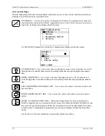
The liquid crystal display (LCD) is an 8-line by 21-character display that provides communication
between the user and a connected device. When the HART Communicator is connected to a SITRANS P
transmitter or other HART-compatible device, the top line of the Online menu displays the model name
of the device and its tag. A typical display is shown below. The actual display content can vary with the
device type and manufacturer.
The bottom line of each menu is reserved for dynamic labels for the software-defined function keys, F1-
F4, which are found directly below the display. More information on software-defined function keys is
given in the next section.
2.3.2 Software-Defined Function Keys
The four software-defined function keys (softkeys), located below the LCD and marked F1 through F4,
are used to perform software functions as indicated by the dynamic labels. Pressing the function key
immediately beneath a label activates the displayed function.
The label appearing above a function key indicates the function of that key for the current menu. For
example, in menus providing access to on-line help, the HELP label appears above the F1 key. In menus
providing access to the Online menu, the HOME label appears above the F3 key. Table 2-1 lists these
labels and describes what happens when each function key is pressed.
SITRANS P
Online
"
1->Pres
2 Type
3 Device setup
HELP |SAVE
Note: If using a Model 375 Field
Communicator, see the inside of
the front cover of this manual.
Summary of Contents for 7MF4033 series
Page 48: ...Model 275 Universal Hart Communicator UMSITRPDS3 1 November 2010 2 26 ...
Page 86: ...Installation UMSITRPDS3 1 November 2010 4 34 ...
Page 152: ...Calibration and Maintenance UMSITRPSD3 1 November 2010 7 20 ...
Page 158: ...Circuit Description UMSITRPDS3 1 November 2010 8 6 ...
Page 197: ......
Page 198: ......
Page 200: ...Model Designations and Specifications UMSITRPDS3 1 November 2010 9 42 ...
Page 204: ...Glossary UMSITRPDS3 1 November 2010 10 4 ...
Page 208: ...Appendix A Online Configuration Map UMSITRPDS3 1 11 4 November 2010 ...
Page 216: ...Appendix C Elevation and Suppression Correction UMSITRPDS3 1 13 4 November 2010 ...


