Installation
UMSITRPDS3-1
November
2010
4-26
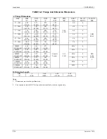
TABLE 4-2 Flange And Extension Dimensions
A. Flange Dimensions
SIZE DIM
“D”
DIM
“BC”
DIM
“T”
DIM
“ED”
DIM
“RF”
BOLT
DIA
NO. OF
BOLTS
FLANGE
PER
2" – 150#
6.00
(152.40)
4.75
(120.65)
0.75
(19.05)
1.95
(49.53)
5/8 4
2" – 300#
6.50
(165.10)
5.00
(127.00)
0.88
(22.23)
1.95
(49.53)
5/8 8
3" – 150#
7.50
(190.50)
6.00
(152.40)
0.94
(23.81)
2.81
(71.37)
0.06
(1.58)
5/8 4
3" – 300#
8.25
(209.55)
6.625
(168.28)
1.13
(28.58)
2.81
(71.37)
3/4 8
ANSI
B16.5
4" – 150#
9.00
(228.60)
7.50
(190.50)
0.94
(23.81)
3.70
(93.98)
5/8 8
4" – 300#
10.00
(254.00)
7.875
(200.03)
1.25
(31.75)
3.70
(93.98)
3/4 8
50MM –
10/16 BAR
6.50
(165.00)
4.92
(125.00)
0.71
(18.00)
M16
4
50MM –
25/40 BAR
6.50
(165.00)
4.92
(125.00)
0.79
(20.00)
M16
4
80MM –
10/16 BAR
7.87
(200.00)
6.30
(160.00)
0.79
(20.00)
Consult
Factory
0.12
(3.00)
M16 8 DIN
2526
80MM –
25/40 BAR
7.87
(200.00)
6.30
(160.00)
0.94
(24.00)
M16
8
TYPE
C
100MM –
10/16 BAR
8.66
(220.00)
7.09
(180.00)
0.79
(20.00)
M16
8
100MM –
25/40 BAR
9.25
(235.00)
7.48
(190.00)
0.94
(24.00)
M20
8
B. Extension Length
DIM
“L”
0
(0.00)
2.00
(50.80)
4.00
(101.60)
6.00
(152.40)
Notes:
1.
Dimensions are in inches (millimeters).
2.
End cap can be rotated 180º for top or bottom vent/drain, side vent option only.
Summary of Contents for 7MF4033 series
Page 48: ...Model 275 Universal Hart Communicator UMSITRPDS3 1 November 2010 2 26 ...
Page 86: ...Installation UMSITRPDS3 1 November 2010 4 34 ...
Page 152: ...Calibration and Maintenance UMSITRPSD3 1 November 2010 7 20 ...
Page 158: ...Circuit Description UMSITRPDS3 1 November 2010 8 6 ...
Page 197: ......
Page 198: ......
Page 200: ...Model Designations and Specifications UMSITRPDS3 1 November 2010 9 42 ...
Page 204: ...Glossary UMSITRPDS3 1 November 2010 10 4 ...
Page 208: ...Appendix A Online Configuration Map UMSITRPDS3 1 11 4 November 2010 ...
Page 216: ...Appendix C Elevation and Suppression Correction UMSITRPDS3 1 13 4 November 2010 ...


