UMSITRPDS3-1
On-Line Operation
November 2010
6-23
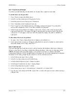
6.4.7 Fixed Current Output
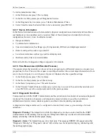
To aid in loop troubleshooting, the transmitter can be placed in a constant current mode.
To enable fixed current operation:
1.
Press 3 Device Setup in the Online menu.
2.
In the Device Setup menu, press 2 Diagnostics/Service.
3.
In the Diagnostics/Service menu, press 2 Simulation.
4.
Press 1 Simulation in the Simulation Test menu.
5.
Press 1 Loop Test in the Simulation menu. A Warning message will appear: “Loop should be
removed from automatic control.” Press OK or ABORT as appropriate.
6.
In the Choose Analog Output Level display, select: 4 mA, 20 mA, other, or End by pressing the
appropriate number key. A message will appear confirming that the output is fixed at the selected
value and a “C” will appear at the lower left of the transmitter display. Press OK or ABORT as
appropriate.
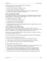
To discontinue fixed current operation:
1.
Navigate to the Choose Analog Output Level display as described above
2.
Select option 4 End. A message will appear stating that the loop can be returned to control and the
transmitter display will no long contain the “C.”
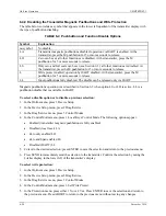
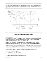
6.4.8 Fault Current
The lower and upper fault currents can be set in this procedure. Both indicate a hardware or firmware
failure, a sensor break, or reaching an alarm limit (diagnostic alarm). In the case of a diagnostic alarm,
ERROR will appear in the transmitter display, as described in Section 6.1.4. (Refer to the HART
Communicator manual or NE 43, Standardization of the Signal Level for Fault Information from Digital
Transmitters with Analog Output Signals, dated 18.01.94 for a detailed error list.)
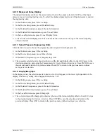
1.
In the Online menu, press 3 Device Setup.
2.
In the Device Setup menu, press 4 Detailed Setup.
3.
In the Detailed Setup menu, press 3 Output Condition.
4.
In the Output Condition menu, press 1 Analog Output.
5.
In the Analog Output menu, press 3 Alarms.
6.
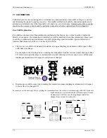
In the Alarms menu, select: 1 AO alarm type, 2 Alarm LRV, or 3 Alarm URV.
7.
Type the new value and press ENTER or press ESC to return to the previous menu without storing a
changed value.
Summary of Contents for 7MF4033 series
Page 48: ...Model 275 Universal Hart Communicator UMSITRPDS3 1 November 2010 2 26 ...
Page 86: ...Installation UMSITRPDS3 1 November 2010 4 34 ...
Page 152: ...Calibration and Maintenance UMSITRPSD3 1 November 2010 7 20 ...
Page 158: ...Circuit Description UMSITRPDS3 1 November 2010 8 6 ...
Page 197: ......
Page 198: ......
Page 200: ...Model Designations and Specifications UMSITRPDS3 1 November 2010 9 42 ...
Page 204: ...Glossary UMSITRPDS3 1 November 2010 10 4 ...
Page 208: ...Appendix A Online Configuration Map UMSITRPDS3 1 11 4 November 2010 ...
Page 216: ...Appendix C Elevation and Suppression Correction UMSITRPDS3 1 13 4 November 2010 ...

