Chapter
4
Technical Information
RFU63x RFID Write/Read Device (UHF)
60
©
SICK AG · Germany · All rights reserved · Subject to change without notice
8014335/YUO7/2016-04-04
Electrical installation
4.8.11
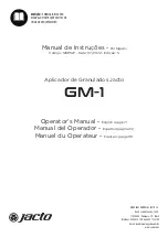
Wiring the "Result 1" switching output in the CDB650-204 connection module
RFU630
CDB650-204
U
IN
* = DC 18 V ... 30 V
Load (e.g. PLC)
Cable
1)
, e.g.
no. 6052286 (2 m)
13
1
.
.
.
20
Res/Out 1
22
GND
5
Shield
U
IN
*
V
S
GND
V
out
Result 1
GND
13
1
2
2
Quenching circuit:
Install an
anti-surge diode
directly at the
load!
For inductive load:
1) Cable:
No. 6052286 (2 m)
No. 6051194 (3 m)
No. 6051195 (5 m)
Ratings for “Result 1” switching output
PNP switching against the supply voltage V
S
(default setting: no function,
logic: not inverted [active high])
– Short-circuit proof + temperature protected
– Galvanically not separate from V
S
0 V ≤ V
out
≤ V
S
(V
S
− 1.5 V) ≤ V
out
≤ V
S
with I
out
≤ 100 mA
Switching
behavior
Features
Electrical
values
3
1
7
2
6
5
4
8
13
14
17
15
9
10
12
16
11
3
1
7
2
6
5
4
8
13
14
17
15
9
10
12
16
11
M12, 17-pin, A-coded
Female
connector
Male
connector