Technical Information
Chapter
4
RFU63x
Electrical installation
8014335/YUO7/2016-04-04
©
SICK AG · Germany · All rights reserved · Subject to change without notice
59
4.8.10
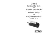
Wiring the "External input 2" switching input in the CDB650-204 connection
module
CDB650-204
18
SGND
8
Shield
14
U
IN
*
17
CDB650-204
PNP sensor
V
S
GND
18
SGND
8
Shield
14
U
IN
*
17
Out
GND
S3
e.g. photo-electric
switch
V
S ext
RFU630
CDB650-204
PNP sensor
V
S
GND
3.32 K
6.64 K
18
SGND
8
Shield
14
U
IN
*
17
Ext. In 2
Ext. In 2
Ext. In 2
Out
GND
S3
e.g. photo-electric switch
CMC600
U
IN
*
GND
S3
U
IN
*
CMC600
CMC600
U
IN
*
a) Sensor supplied by CDB650-204
b) Sensor connected electrically isolated and externally supplied
d) Switch connected electrically isolated and externally supplied
c) Switch supplied by CDB650-204
Connect the switch as shown in b)
Serial Aux
(RS-232)
ON
OFF
S3 : SGND-GND
No
YES
S4 : CMC
ON
OFF
S3 : SGND-GND
No
YES
S4 : CMC
No
YES
S4 : CMC
ON
OFF
S3 : SGND-GND
V
in
V
in
V
in
„External
input 2“
U
IN
* = DC 18 V ... 30 V
V
in
= max. 30 V
SensGND
SensGND
SensGND
Switch S3: SGND-GND
ON:
GND of the sensor connected to GND
of
CDB650-204/CMC600.
OFF:
Sensor connected electrically isolated
to the CDB650-204/CMC600.
Reference potential valid for all switching
inputs (“Sensor 1/2” and “In 1/2”)
Function assignment to “External input 2” switching
input via SOPAS:
- Start of reading clock
- Stop of reading clock
- if required further functions in the future
Software-controlled, the CMC600 transfers the
switching status of its physical “Ext. In 2” input
automatically via the cable to the serial Aux data
interface of the RFU630.
The RFU630 converts the status internally to its
logical “External input 2”.
Ratings for “External input 2”
(“Ext. In 2” switching input)
Power fed to the input starts the
assigned function, e.g. stop of reading
clock.
(default setting: logic not inverted
[active high], debouncing 10 ms)
– Optodecoupled, reverse polarity
protected
– Can be wired with the PNP output of
a sensor
– SensGND is the shared isolated
ground of all switching inputs
Low: V
in
≤ 2 V; I
in
≤ 0.3 mA
High: 6 V ≤ V
in
≤ 30 V;
0.7 mA ≤ I
in
≤ 5 mA
Switching
behavior
Features
Electrical
values