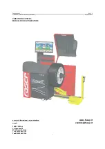
Operator's Manual
S 63 E - S 63 E C
109
24
WARNING
The machine allows the operator to select how to apply the adhesive weight (CLIP or at
6 o'clock), depending on his requirements.
To change the application position for the adhesive weights, follow the instructions in
the set up menu "Adhesive weight application position”.
• Manually applied adhesive weights with laser device enabled (if provided)
1 Select the first side to be balanced
2 Turn the wheel until the central element of the corresponding position indicator lights
up together with the laser line
3 Apply the adhesive weight manually in the position in which the relative plane was
measured, using the centre of gravity of the weight itself as reference. In this phase,
one display shows the unbalance value of the side to be balanced and the other shows
the message "H.6" that indicates the correct application position as shown in figure 24.
• Adhesive weights applied manually, without a weight-holder device ("CLIP adhesive
weight application position" enabled)
1 Select the first side to be balanced
2 Turn the wheel until the central element of the corresponding position indicator lights
up. Keeping the wheel in position with the clamping brake, a display will now show
the quantity of the weight to be applied in gr/ounces and the other will display the
distance in mm alternatively to the plane identification abbreviation (A-1 for Inner
Plane/A-2 for Outer Plane)
3 Move the sensor until it reaches the signalled position. During this phase, the unbal-
ance value of the side to be balanced is shown on one display, whereas the numerical
value updated according to the sensor position, which becomes zero when the position
for application of the weight is reached, is shown on the other display.
4 Manually apply the adhesive weight, taking the centre of the gripper cavity as the
reference for the midway point of the weight.
Summary of Contents for S 63 E
Page 71: ...Manuale d uso S 63 E S 63 E C 71 SCHEMA PNEUMATICO Alimentazione Aria 7 10 bar 100 145 psi ...
Page 89: ...Operator s Manual S 63 E S 63 E C 89 9b DISPLAY PANEL ...
Page 140: ...140 S 63 E S 63 E C Operator s Manual PNEUMATIC DIAGRAM Air supply 7 10 bar 100 145 psi ...
Page 158: ...158 S 63 E S 63 E C Manuel d utilisation 9b PANNEAU D AFFICHAGE ...
Page 227: ...Benutzerhandbuch S 63 E S 63 E C 227 9b ANZEIGEFELD ...
Page 281: ...Benutzerhandbuch S 63 E S 63 E C 281 PNEUMATIKSCHEMA Luftversorgung 7 10 bar 100 145 psi ...
Page 299: ...Manual de uso S 63 E S 63 E C 299 9b PANEL VISOR ...
Page 352: ...352 S 63 E S 63 E C Manual de uso ESQUEMA NEUMÁTICO Alimentación Aire 7 10 bar 100 145 psi ...
Page 353: ...S 63 E S 63 E C 353 Note ...
Page 354: ...354 S 63 E S 63 E C Note ...
Page 355: ......


