background image

R..7, F..7, K..7, S..7, Spiroplan

® 

W Gear Units – Operating Instructions

55

8

Mounting Positions

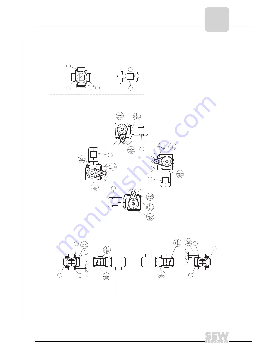
SA/SH47-97

28 021 100

 page 36

M4

M3

M5

M6

M2

M1

*

*

*

*

1

x

x

90°

A

x

B

180°

270°

x

3

2

270°

90°

x

180°

x

x

x

x

270°

180°

90°

x

x

x

x

x

x

A

B

B

A

M1 … M6

M1 … M6

Summary of Contents for F 27 Series

Page 1: ...04 2000 Gear Units R 7 F 7 K 7 S 7 Series Spiroplan W Edition 05 2001 Operating Instructions 10503013 EN...

Page 2: ...SEW EURODRIVE...

Page 3: ...shaft mounted gear units with shrink disc 23 4 9 Installation of the AM adapter coupling 25 4 10 Installation of the AQ adapter coupling 27 4 11 Installation on the AD input shaft assembly 28 5 Start...

Page 4: ...tion bearing of gear units as stell scrap The same applies to gray cast iron parts unless there is separate collection service Some worm gears are made of non ferrous metals and must be disposed of ac...

Page 5: ...rom incorrect use incorrect installation or operation removal of required protective covers or the housing when this is not permitted Designated use These geared motors gear units are intended for ind...

Page 6: ...ten out for unusual grinding noises as the shaft rotates Secure the shaft keys for test mode without output elements Do not render monitoring and protection equipment inoperative even for test mode Sw...

Page 7: ...25 88 521 522 523 6 37 506 507 508 39 131 31 24 22 517 516 515 1 Pinion 19 Key 42 Deep groove ball bearing 507 Shim 2 Gear 20 Breather valve 43 Key 508 Shim 3 Pinion shaft 22 Gear unit housing 45 Deep...

Page 8: ...Deep groove ball bearing 92 Disc 506 Shim 3 Pinion shaft 30 Tapered roller bearing 93 Lock washer 507 Shim 4 Gear 31 Lockwasher 94 Hex head screw 508 Shim 5 Pinion shaft 32 Spacer tube 100 Cover 515...

Page 9: ...m 2 Gear 30 Tapered roller bearing 113 Wing nut 533 Shim 3 Pinion shaft 31 Key 114 Locking plate 534 Shim 4 Gear 37 Tapered roller bearing 116 Thread retention 535 Shim 5 Pinion shaft 39 Circlip 119 S...

Page 10: ...523 522 521 19 2 59 102 101 59 20 22 1 100 61 1 Pinion 19 Key 61 Circlip 507 Shim 2 Gear 20 Breather valve 88 Circlip 518 Shim 5 Worm 22 Gear unit housing 89 Cap 519 Shim 6 Worm gear 25 Tapered rolle...

Page 11: ...50 251 17 7 11 8 69 518 518 518 12 9 101 1 Pinion 19 Key 88 Circlip 251 Circlip 6 Gear 22 Gear unit housing 89 Cap 518 Shim 7 Output shaft 25 Deep groove ball bearing 100 Gear unit cover 519 Shim 8 Ke...

Page 12: ...worm Spiroplan W gear units no large external mass moments of inertia which could exert a retrodriving load on the gear unit where h retrodriving 2 1 0 5 self locking 4 3 Preliminary work The output...

Page 13: ...icant fill levels or data on nameplate In case of mounting position change adjust lubricant filling quantities accordingly Please consult our service department if the mounting position for K gear uni...

Page 14: ...geared motors for long term storage pivoting or inclined mounting positions the supplied breather valve is located in the motor terminal box With gear head units that have to be vented on the input si...

Page 15: ...ing input and output elements Use the center bore and the thread on the shaft end for positioning purposes Power transmission elements should be balanced after fitting and must not give rise to any im...

Page 16: ...llowing factors according to the manufacturer s recommendation when installing couplings a maximum and minimum distance b axial misalignment c angular misalignment 03356AXX Fig 6 Distance and misalign...

Page 17: ...shaft mounted gear units Do not strain torque arms during installation Parallel shaft helical gear units Helical bevelgear units Bushing with bearings on both ends 1 Install connection end B as a mir...

Page 18: ...ons Mechanical Installation Helical worm gear units Bushing with bearings on both ends 1 SPIROPLAN W gear units Bushing with bearings on both ends 1 01031CXX Fig 9 Torque arm for helical worm gear uni...

Page 19: ...te NOCO fluid evenly 3 Install shaft and secure axially installation will be made easier by using a mounting device 3A Installation with standard components Note the construction notes in the Geared M...

Page 20: ...ighten retaining screw with corresponding torque see table 03362BXX 1 retaining screw 2 lock washer 3 washer 4 circlip 6 customer shaft with contact shoulder 03363AXX 1 retaining screw 2 lock washer 3...

Page 21: ...s 2 to 4 and the spacer tube 5 if installed 3 Install the removal washer 8 and the locknut 7 from the SEW installation removal kit between customer shaft 6 and circlip 4 4 Reinstall the circlip 4 5 Re...

Page 22: ...M6 5 6 15 5 5 5 22 5 19 7 25 643 683 8 FA 27 SA 47 25 M10 5 10 20 7 5 28 24 7 35 643 684 6 FA 37 KA 37 SA 47 SA 57 30 M10 5 10 25 7 5 33 29 7 35 643 685 4 FA 47 KA 47 SA 57 35 M12 5 12 29 9 5 38 34 7...

Page 23: ...drive shaft 01815AXX 01816AXX 3 Apply NOCO fluid in the bushing area onto the input shaft1 4 Install shaft making sure that the locking collars of the shrink disc are evenly spaced2 01817AXX 01818AXX...

Page 24: ...isc off the hub Cleaning and lubricating the shrink disc There is no need to take apart and re grease disassembled shrink discs before they are screwed back on The shrink disc only needs to be cleaned...

Page 25: ...acer tube 491 on motor shaft and install supplied key 484 3 Heat coupling half 479 to approx 80 100 C slide coupling half on motor shaft IEC adapters until rest on motor shaft shoulder NEMA adapters u...

Page 26: ...ed key size AM280 only 3 Heat coupling half 479 to 80 C 100 C and slide on motor shaft A 139 mm 4 Fasten coupling half with setscrew and check position distance A 5 Mount motor on adapter the gearing...

Page 27: ...oupling half with setscrew 6 Check position of coupling half distance A see table Mount motor to adapter the jaws of both coupling halves must enmesh The insertion force required to join the coupling...

Page 28: ...ing plate shaft extensions must be aligned and secure it 3 Mount drive elements onto input shaft extension and install motor shaft align these to each other correct motor position where necessary 4 In...

Page 29: ...screws and apply an adhesive agent e g Loctite 243 to the first turns on the screw 5 Set component onto centering shoulder and fasten retaining screws with indicated tightening torque Tt see table AD...

Page 30: ...no special startup notes that have to be observed for helical gear units parallel shaft helical gear units and helical bevel gear units if the gear units have been mounted according to the section Me...

Page 31: ...ee DIN 3761 A Defective rubber gasket on gear unit cover B Defective gasket C Gear unit not vented A Retighten screws on gear unit cover and observe gear unit Oil still leaking Call customer service B...

Page 32: ...following illustration at least every three years Replace mineral oil Replace bearing grease depending on operating conditions see following illustration at least every five years Replace synthetic o...

Page 33: ...the oil is visibly contaminated it is recommended to change it sooner than re commended by the maintenance intervals listed under the heading Inspection and maintenance periods on page 32 4 For gear...

Page 34: ...General comments on mounting positions Mounting position designation SEW has six mounting positions M1 M6 for gear units see illustration 03203AXX Fig 13 Mounting positions M1 M6 M1 M1 M1 M1 M1 M1 M4...

Page 35: ...F RF RXF M1 M2 M3 M4 M5 M6 F FA B FH B FV B FF FA FH FV FAF FHF FVF FAZ FHZ FVZ K KA B KH B KV B K KH 166 167 186 187 KF KA KH KV KAF KHF KVF KAZ KHZ KVZ S SF SA SH SAF SHF SAZ SHZ B3 V6 B8 V5 B6 B7 B...

Page 36: ...s their meaning Churning losses There is a possibility of increased churning losses with some mounting positions Please contact SEW when dealing with the following combinations Symbol Meaning Breather...

Page 37: ...ns 37 8 Mounting Positions 8 3 Mounting positions helical gear units R17 R167 04 040 100 page 36 270 0 90 180 1 2 3 R47 R57 R17 R27 R17 R27 R47 R57 M5 M4 M5 M1 M3 M5 M6 M1 M3 R17 M6 M2 0 270 90 180 0...

Page 38: ...Units Operating Instructions Mounting Positions RF17 RF167 04 041 100 page 36 M4 M1 M2 M3 M5 M6 RF17 RF17 RF27 RF17 RF27 RF47 RF57 M1 M3 M5 M6 M5 1 3 2 270 90 0 180 90 180 270 0 90 0 270 180 0 0 0 0 x...

Page 39: ...R17F R87F 04 042 100 page 36 Caution Note the notes in the Geared Motors catalog section Project Planning Gear Units Overhung and axial loads M6 M5 M4 M3 M2 M1 R47F R57F R17F R27F R17F R27F R47F R57F...

Page 40: ...K 7 S 7 Spiroplan W Gear Units Operating Instructions Mounting Positions RX57 RX107 04 043 100 page 36 M1 M2 M3 M4 M5 M6 3 1 2 0 0 90 270 180 0 0 0 0 180 90 270 0 90 180 270 x x x x x x x x x x x x x...

Page 41: ...7 Spiroplan W Gear Units Operating Instructions 41 8 Mounting Positions RXF57 RXF107 04 044 100 page 36 M3 M6 M5 M4 M1 M2 1 3 2 0 0 0 0 270 180 0 90 0 180 270 90 0 90 270 180 x x x x x x x x x x x x x...

Page 42: ...Positions 8 4 Mounting positions parallel shaft helical gear units F FA B FH27B 157B FV27B 107B 42 042 100 page 36 M2 M4 M1 M3 M6 M5 F47 180 0 90 1 270 3 2 270 0 180 90 0 0 0 0 0 180 90 270 x x x x x...

Page 43: ...tructions 43 8 Mounting Positions FF FAF FHF FAZ FHZ27 157 FVF FVZ27 107 42 043 100 page 36 M1 M6 M5 M3 M4 M2 FF47 2 90 0 180 1 3 270 90 270 180 0 0 270 90 180 0 0 0 0 x x x x x x x x x x x x x x M1 M...

Page 44: ...Operating Instructions Mounting Positions FA FH27 157 FV27 107 42 044 100 page 36 0 0 270 90 180 M3 M5 0 180 90 M4 270 M6 FA47 M1 M2 3 1 2 0 270 180 90 0 0 0 x x x x x x x x x x x x x x M1 M3 M5 M6 M...

Page 45: ...cal bevel gear units K KA B KH37B 157B KV37B 107B 34 025 100 page 36 Caution Note the notes in the Geared Motors catalog section Project Planning Gear Units Overhung and axial loads K47 M1 M2 M4 M3 M5...

Page 46: ...ions K167 187 KH167B 187B 34 026 100 page 36 Caution Note the notes in the Geared Motors catalog section Project Planning Gear Units Overhung and axial loads M1 M2 M6 M5 M3 M4 1 B A 0 90 180 270 3 2 2...

Page 47: ...Operating Instructions 47 8 Mounting Positions KF KAF KHF KAZ KHZ37 157 KVF KVZ37 107 34 027 100 page 36 M5 M6 M4 M3 M2 M1 KF47 KF47 0 90 A 270 180 B 1 x 3 x 2 180 x 0 x 270 x 90 A B A B 270 0 x x 180...

Page 48: ...n W Gear Units Operating Instructions Mounting Positions KA KH37 157 KV37 107 39 025 100 page 36 1 x x x 3 x 2 90 0 A 180 B 270 M5 M3 M6 M2 M4 M1 KA47 KA47 B A 270 0 x x 180 90 x x x x x 180 x 270 x 0...

Page 49: ...roplan W Gear Units Operating Instructions 49 8 Mounting Positions KH167 187 39 026 100 page 36 M1 M2 M6 M5 M3 M4 B 90 x 0 180 x 270 x A 3 1 x 2 90 x x 180 0 270 x x 270 x 0 180 90 x x x A B A B x x 0...

Page 50: ...nting positions helical worm gear units S37 05 025 100 Caution Note the notes in the Geared Motors catalog section Project Planning Gear Units Overhung and axial loads M1 M2 M3 M4 M5 M6 1 B A x 0 90 x...

Page 51: ...g Positions S47 S97 05 026 100 page 36 Caution Note the notes in the Geared Motors catalog section Project Planning Gear Units Overhung and axial loads M1 M2 M3 M5 M6 M4 1 B A x 0 90 x 180 x 270 3 x 2...

Page 52: ...7 Spiroplan W Gear Units Operating Instructions Mounting Positions SF SAF SHF37 05 027 100 M1 M4 M3 M2 M6 M5 A B 1 x 3 2 90 x 180 x 0 x 270 270 x x x 0 180 90 x B A A B 0 0 0 0 x x x x x 0 x 180 90 x...

Page 53: ...Gear Units Operating Instructions 53 8 Mounting Positions SF SAF SHF SAZ SHZ47 97 05 028 100 page 36 M5 M2 M4 M1 M3 M6 x 90 x 0 A 180 270 x B 1 x 3 2 x 0 x 270 x A x 90 180 B 0 0 x x 0 0 x x x 0 270 1...

Page 54: ...7 S 7 Spiroplan W Gear Units Operating Instructions Mounting Positions SA SH37 28 020 100 M1 M4 M2 M3 M6 M5 1 A x 0 90 x 180 B x 270 3 x 2 x 0 x x 180 90 270 x 180 x 90 0 270 x 0 0 x 0 0 x x x B A A...

Page 55: ...oplan W Gear Units Operating Instructions 55 8 Mounting Positions SA SH47 97 28 021 100 page 36 M4 M3 M5 M6 M2 M1 1 x x 90 A 0 x B 180 270 x 3 2 270 90 x 180 x 0 x x 0 x 270 180 90 x 0 0 0 0 x x x x x...

Page 56: ...llution class WGK 1 HCE Synthetic hydrocarbons diester oil USDA H1 approval HLP Hydraulic oil Synthetic lubricant anti friction bearing grease on synthetic base Mineral lubricant anti friction bearing...

Page 57: ...Renolin CLP 680 Optigear BM 680 Meropa 680 Tribol 1100 680 Synlube CLP 680 Synlube CLP 220 Multifak 6833 EP 00 Multifak EP 000 Tribol 800 680 Renolin CLP 150 Renolin SF 7 041 Optigear BM 100 Meropa 10...

Page 58: ...47 15 4 40 46 5 48 52 39 5 41 R167 27 70 82 78 88 66 69 Gear units RF Fill quantity in liters M11 1 The larger gear unit in multi stage gear units must be filled with the larger oil quantity M21 M3 M4...

Page 59: ...Gear units Fill quantity in liters M1 M2 M3 M4 M5 M6 FF27 0 6 0 8 0 7 0 7 0 6 0 6 FF37 1 1 2 0 7 1 3 1 1 1 FF47 1 6 1 9 1 1 1 9 1 5 1 7 FF57 2 8 3 8 2 1 3 7 2 9 3 FF67 2 7 3 8 1 9 3 8 2 9 3 2 FF77 5...

Page 60: ...170 205 130 130 Gear units Fill quantity in liters M1 M2 M3 M4 M5 M6 KF37 0 5 1 1 1 1 1 5 1 1 KF47 0 8 1 3 1 7 2 2 1 6 1 6 KF57 1 3 2 3 2 7 3 2 9 2 7 KF67 1 1 2 4 2 8 3 6 2 7 2 7 KF77 2 1 4 1 4 4 6 4...

Page 61: ...77 1 9 4 2 3 7 5 4 6 4 4 4 4 S87 3 3 8 1 6 9 10 4 12 8 4 8 4 S97 6 8 15 13 4 18 22 5 17 17 Gear units Fill quantity in liters M1 M2 M31 1 The larger gear unit in multi stage gear units must be filled...

Page 62: ...ction Sales Service Haguenau SEW USOCOME SAS 48 54 route de Soufflenheim B P 185 F 67506 Haguenau Cedex Tel 03 88 73 67 00 Fax 03 88 73 66 00 http www usocome com sew usocome com Assembly Sales Servic...

Page 63: ...ditional addresses for service in Canada provided on request Chile Assembly Sales Service Santiago de Chile SEW EURODRIVE CHILE Motores Reductores LTDA Panamericana Norte No 9261 Casilla 23 Correo Qui...

Page 64: ...87 sew baroda gecsl com Ireland Sales Service Dublin Alperton Engineering Ltd 48 Moyle Road Dublin Industrial Estate Glasnevin Dublin 11 Tel 01 8 30 62 77 Fax 01 8 30 64 58 Italy Assembly Sales Servic...

Page 65: ...deros 120 124 Urbanizacion Industrial Vulcano ATE Lima Tel 511 349 52 80 Fax 511 349 30 02 sewperu terra com pe Poland Sales Lodz SEW EURODRIVE Polska Sp z o o ul Pojezierska 63 91 338 Lodz Tel 042 6...

Page 66: ...l 061 4 17 17 17 Fax 061 4 17 17 00 http www imhof sew ch info imhof sew ch Thailand Assembly Sales Service Chon Buri SEW EURODRIVE Thailand Ltd Bangpakong Industrial Park 2 700 456 Moo 7 Tambol Donhu...

Page 67: ...e USA provided on request Venezuela Assembly Sales Service Valencia SEW EURODRIVE Venezuela S A Av Norte Sur No 3 Galpon 84 319 Zona Industrial Municipal Norte Valencia Tel 58 241 8 32 98 04 Fax 58 24...

Page 68: ...SEW EURODRIVE GmbH Co P O Box 3023 D 76642 Bruchsal Germany Phone 49 7251 75 0 Fax 49 7251 75 1970 http www sew eurodrive com sew sew eurodrive com...

Reviews: