40
SESAMO
DUALCORE
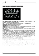
Installation with selector for RD100 versions
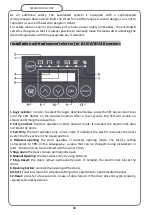
Logic selection
: to select the logics described below, press the desired logic button. The LED
will remain on steady confirming the acquisition.
1 T
: Test button for checking the operation of the automated system safety devices
2 Opening button:
controls the opening of the doors
3 Stop open
: the doors remain permanently open
4 Exit Only
: the doors operate only in exit mode. If installed, the electric lock does not block
the doors. The motors hinder the manual opening of the doors.
5 Entry and Exit
: the doors operate in entry and exit mode. If installed, the electric lock does
not block the doors.
Key:
the key performs the night lock function. By turning the key to perform the night lock, the
doors are set to closing mode and the electric lock, if present, locks the doors. In the absence
of the electric lock, the motors hinder the manual opening of the doors. The selector indicates
the night lock position by flashing the LED of the last selected logic. By bringing the key to the
daytime position, the doors will perform two opening/closing cycles to check the operation of
the automatic safety systems, after which the door is ready to operate according to the
previously set logic. If the door does not work properly, request technical assistance.
PR
Used by technical personnel for parameter adjustments
ESC
Used by technical personnel for parameter adjustments
Reset:
press for a few seconds in case of door failure. If the door does not work properly,
request technical assistance.
Battery Signal Led:
if on and steady, it indicates the absence of mains power and the
consequent battery operation of the automated system. If on and flashing, it indicates that the
battery charge level is insufficient. In this case, if the LED does not go off after a few hours, the
batteries must be replaced; request technical assistance.
Summary of Contents for DUALCORE LH100
Page 1: ...LH100 LH140 RD100 ENGLISH AUTOMATED SYSTEMS FOR SLIDING DOORS INSTALLATION MANUAL ...
Page 44: ...44 SESAMO DUALCORE Fig A Fig B ...
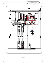
Page 45: ...45 SESAMO DUALCORE Fig 1 ...
Page 46: ...46 SESAMO DUALCORE Fig 2 ...
Page 47: ...47 SESAMO DUALCORE Fig 3 ...
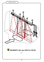
Page 48: ...48 SESAMO DUALCORE WARNING Exit way ONLY for RD100 Fig 4 ...
Page 49: ...49 SESAMO DUALCORE Fig 5 ...
Page 50: ...50 SESAMO DUALCORE Fig 5 A ...
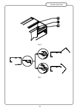
Page 51: ...51 SESAMO DUALCORE Fig 6 Fig 7 ...
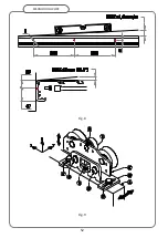
Page 52: ...52 SESAMO DUALCORE Fig 8 Fig 9 ...
Page 53: ...53 SESAMO DUALCORE Fig 9a Fig 10 ...
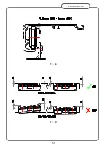
Page 54: ...54 SESAMO DUALCORE Fig 11 Fig 12 ...
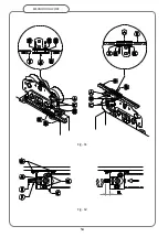
Page 55: ...55 SESAMO DUALCORE Fig 13 Fig 14 Fig 15 ...
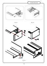
Page 56: ...56 SESAMO DUALCORE Fig 16 Fig 16a ...
Page 57: ...57 SESAMO DUALCORE Fig 17 Fig 17a ...
Page 58: ...58 SESAMO DUALCORE Fig 18 Fig 19 Fig 20 ...
Page 59: ...59 SESAMO DUALCORE Fig 21 Fuses 6 3A T J ...
Page 60: ...60 SESAMO DUALCORE Fig 22 ...
Page 61: ...61 SESAMO DUALCORE Fig 23 1 Fig 23 2 ...
Page 62: ...62 SESAMO DUALCORE Fig 24 PARAMETER 30 1 ...
Page 63: ...63 SESAMO DUALCORE Fig 25 PARAMETER 30 1 Exit way ...
Page 64: ...64 SESAMO DUALCORE Fig 25 A ...
Page 65: ...65 SESAMO DUALCORE Fig 26 ...
Page 66: ...66 SESAMO DUALCORE Fig 27 PARAMETER 31 1 ...
Page 67: ...67 SESAMO DUALCORE Fig 28 PARAMETER 31 0 ...
Page 68: ...68 SESAMO DUALCORE Fig 29 ...
Page 69: ...69 SESAMO DUALCORE Fig 30 Fig 31 ...
Page 71: ...71 SESAMO DUALCORE Fig 33 ...
Page 72: ...72 SESAMO DUALCORE Fig 34 ...


