background image


29 


SESAMO


DUALCORE


40 

Not managed 


41 

Opening delay 

0 - 99 adjustment step 0.1 second  

0  

42 

Start = Safe close 

0 Safe close  does not  activate opening with door 
closed 
1 Safe close activates opening with door closed 


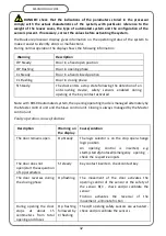
 DANGER: parameter 34 must be set to 0 as the default for the correct operation of 

the board. Otherwise it may cause damage to the control unit.  


NOTE: 

With parameter 33 set to 0, the selector does not signal when the battery is low. If 

you want to have a low battery signal on the selector, select a value other than 0 according 
to the desired behavior in the absence of mains power. For RD100 versions the value is set 
at level 3 by the Main Key SM 


NOTE: 

With AUX IN set to Semiautomatic mode, the opening control can be given via Start1 

or Start2 while the closing control must be given via AUX IN (not usable on RD100) 


NOTE: 

With AUX OUT set to Ringer mode, the AUX OUT output will be activated for about 2 

seconds  following  the  activation  in  succession  of  the  Start1  and  Safe  Close  1  control.  This 
function is disabled in the Stop Closed and 1 Radar logic. 


NOTE: 

With  Key  set  as  monostable,  use  NO  contact  between  terminal  boards  22/23  and 

parameter 28 at level 1 
 

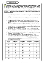
PARAMETERS FACTORY SETTING


It is possible to restore all the values of the control unit to the factory settings by executing a 
default 

Sd

 set as described below: 

1-


press the - key on the display until 

Sd

 appears then press ENT: the display will 

show code --; 

2-


press again and hold the ENT (about 5 seconds) until the display turns off for a 
moment, then release the ENT key. 

3-


the display shows information on: type of firmware User controller, main key, 
firmware safety controller, sensor configuration and finally displays E1 flashing; 

4-


the control unit parameters have returned to the factory settings except for the LS 
setting which remains the one previously stored;  

5-


repeat the LP and/or LS procedures  

Summary of Contents for DUALCORE LH100

Page 1: ...LH100 LH140 RD100 ENGLISH AUTOMATED SYSTEMS FOR SLIDING DOORS INSTALLATION MANUAL ...

Page 2: ...undertaken the type of system use traffic forces and inertia in play Always pay particular attention to the areas that could lead to crushing shearing conveying and any other hazard in general by placing appropriate signs if necessary Include the identification data of the motorized door on each installation Check that the electrical network to which the system is corrected is of the right size an...

Page 3: ...n of the electric lock installation of the emergency release lever 13 cover fixing 14 mechanical assembly final checks Dualcore processor function and warnings 15 electronic control unit description 16 processor sensors compliant with EN16005 17 settings and connections for RD100 version 19 terminal board connections EN16005 20 automated system commissioning 22 parameter acquisition procedure LP 2...

Page 4: ...e 2006 42 CE conforms with the essential safety requirements indicated in appendix I of the directive with the exception of the following points 1 2 4 3 1 2 4 4 1 3 4 1 3 5 1 3 7 1 3 8 2 1 4 1 5 3 1 5 7 1 5 14 1 5 15 1 5 16 complies with the conditions of the following other CE Directives 2014 30 UE Electromagnetic Compatibility 2014 35 UE Low Voltage and that the following parts clauses of agreed...

Page 5: ...installed on exit ways in compliance with the requirements of EN 16005 standard paragraph 4 7 2 RD100 adopts some components in redundant form and is equipped with two gearmotors and two electronic control units The two control units Master G Slave P fig 5 A allow continuous and crossed monitoring of the operation and a special algorithm assigns control to one control unit in case the other is fau...

Page 6: ...on of the system in case of emergency 15 The user must refrain from any attempt to repair or direct intervention and contact only qualified personnel are allowed 16 The installation must be done only by qualified and experienced personnel and in full compliance with current regulations 17 Anything that is not expressly provided in these instructions is not allowed 18 This manual is intended for qu...

Page 7: ...oints inside the automated system to allow connection with external peripheral devices Use the notch on the head for the passage of the mains power cable or make one inserted in the aluminum profile as shown in fig 34 Protect the cable with the special rubber supplied DANGER do not damage the cable during the described fixing activities PARTS DESCRIPTION The LH100 LH140 automated systems consist o...

Page 8: ...screws then remove the cover following the sequence shown in fig 7 Remove the carriages following the procedure below disconnect the belt attachment bracket from the carriage ref A fig 11 by undoing screws C loosen the screw of the anti derailing roller ref D fig 9 and lower it fully remove the carriage To make it easier to fix the case to the wall the internal components can be moved or removed b...

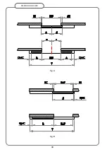
Page 9: ...ay so that the two leaves meet in the center of the opening Fig A A In the case of a single leaf door respect the indications and the machine quotients shown in Fig B Extendible crossbeams unused areas of the case should be positioned with the extensions added to the QMC and QMT For the abbreviations used in fig A and B refer to the list below Lup Usable doorway width A Sliding leaf width St Mount...

Page 10: ...ent a risk Ensure that the anti derailing wheels fig 9 ref E are fully lowered Lift the leaf and place the wheels of the carriages delicately on the guide rail taking care not to damage the parts by dropping or banging them DOOR ADJUSTMENT The leaves can be adjusted on three axes x y z according to the requirements of the installation LATERAL ADJUSTMENT Y FIG 9 FIG 10 loosen the screws F and slide...

Page 11: ...the one without joint so that the comb B allows the belt E to be moved Move the clamp to the desired position Tighten the screws D ensuring that the teeth of the belt E sit correctly in the slots in the comb B BELT ASSEMBLY AND TENSIONING to adjust the tension of the belt proceed as follows ref fig 12 ensure that the motor group is positioned and fixed according to the default set up and is in a p...

Page 12: ...ng out of control when in movement and presenting a serious risk of injury WARNING incorrect adjustment of the anti derailing device that leaves the wheel in contact with the aluminum profile causes excessive wear and noise during operation DOOR LIMIT SWITCH ADJUSTMENT Position the limit switches of the leaves as shown in fig 5 making sure that in the case of two leaves the central limit switch ac...

Page 13: ...stalled secure the emergency release cable by following the instructions below fig 17 before proceeding with the assembly make sure that spring D is correctly inserted in pipette A insert stop B at the end of the cable under bracket C and pass it through the appropriate slot secure spring D between bracket C and F insert the threaded part E of pipette A of the appropriate compartment on bracket F ...

Page 14: ...ts H with an Allen wrench H Check that the release handle works correctly and that it has sufficient space to open and fully release the electric lock If the tension of the cable needs to be adjusted do so via the tensioner of the lever or the nut of the pipette on board the electric lock At the end of the checks cut the steel cable DANGER carefully test the correct function of the release lever A...

Page 15: ...dentify any points with excessive friction DUALCORE PROCESSOR FUNCTION AND WARNINGS The Dualcore processor is designed to manage automated systems produced by Sesamo complies with the specifications of EN16005 and can function with peripherals that comply with the same regulation in order to allow the creation of fully automated doors in line with the highest safety standards The Dualcore processo...

Page 16: ... input for PC connection through the appropriate optional signal converter made by Sesamo B terminal block set up for connections to additional peripheral devices and accessories C connector for motor encoder connection D connector for motor power supply connection E connector for battery connection connect only on the Master board for RD100 version WARNING check the correct orientation of the bat...

Page 17: ...pole L1 fig 22 and the surface of the automated system crossbeam If this is not the case an important safety feature of the entire system may be compromised with a risk of electric shock or malfunctions in the product PROCESSOR SENSORS COMPLIANT WITH EN16005 WARNING the P56001 control unit CANNOT WORK with photocells connected directly to the terminal board The direct connection and switching on o...

Page 18: ...g values of the contacts NO NC WARNING LH100 LH140 versions for connections with B C sensors model VIO DT1 2 IXIO DT1 see fig 24 for connections with Axis T model B C sensors see fig 26 RD100 version for connections with sensor B model IXIO DT3 and sensor C model VIO DT1 2 IXIO DT1 see diagram fig 25 LH100 LH140 RD100 versions for connections with A D sensors model PRESENCE T see diagram fig 28 or...

Page 19: ...l part S The Master and Slave control units must be connected together as shown in fig 25 Parameters set only on Master control unit parameter 21 Start2 input polarity set to 1 NC parameter 27 Aux In2 input polarity set to 1 NC parameter 13 type electric lock for RD100 version set to 4 Bistable To complete the setting and keep the ENT button pressed for 5 seconds WARNING for the RD100 automated sy...

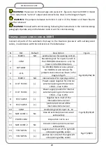
Page 20: ...LH100 LH140 versions only for input 1 in the RD100 version 3 OPTOREF For LH100 LH140 versions jumper For RD100 version remove the jumpers and connect as shown in the diagram fig 25 4 OO 5 START2 NO internal sensor for opening control 6 OUT 15VDC Power supply negative for internal external opening control sensors 15Vdc max 0 25A 7 OUT 15VDC Power supply positive for internal external opening contro...

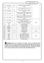
Page 21: ...N 2 NC area A4 left side opening safety sensor 19 OUT 15VDC Positive power supply right left side opening safety sensor 15Vdc max 0 25A 20 OUT 15VDC Negative power supply right left side opening safety sensor 15Vdc max 0 25A 21 OUT 15VDC Negative peripheral device supply 15Vdc max 0 25A Fig 31 22 OUT 15VDC COM Negative peripheral device supply 15Vdc max 0 25A additional standard signal 23 KEY NC n...

Page 22: ...the passage of the mains cable from inside to outside of the automated system WARNING if no optional device for night closing control is installed make sure that the KEY input is shorted out with the appropriate COM input terminals 22 and 23 conversely it is not possible to start the automated system For RD100 model the connection to the KEY input is in series with the selector switch Make sure th...

Page 23: ... 7 the Lp procedure is enabled and the automated system performs some openings and closings max 5 useful for measuring the parameters at the end the leaves are positioned completely open and the display shows Op 8 proceed with the connection of the safety sensors and the subsequent LS procedure SENSORS ACQUISITION PROCEDURE LS The sensor acquisition procedure LS learn sensors allows the Dualcore c...

Page 24: ...lose the cover of the automated system check that the sensors are in the correct position clear the detection area by removing any obstacles under the sensors note it is possible to reset the count by pressing the ESC key and immediately passing to step 4 4 after about 60 sec the control unit acquires the sensors in about 10 sec it is possible to recognize the end of the LS procedure when the sens...

Page 25: ...On break Active On break On break F5 On break Active On break Active F6 On break Active Active On break F7 On break Active Active Active F8 Active On break On break On break F9 Active On break On break Active FA Active On break Active On break Fb Active On break Active Active FC Active Active On break On break Fd Active Active On break Active FE Active Active Active On break FF Active Active Activ...

Page 26: ...alue with the or keys and then press ENT to confirm the chosen value the value is stored by the control unit and the display returns to showing the modified parameter 4 if you want to change other parameters proceed from point 1 or press ESC to end the procedure the segments of the display begin to rotate and after few seconds the display shows the status of the CL door door closed NOTE if the key...

Page 27: ...y opening 4 Repeat Start control 2 5 Semi automatic 6 Stop movement 7 Single control for partial opening 8 Set partial opening on all inputs 9 Semi automatic with automatic closing 1 16 Auxiliary input 2 configuration 0 Emergency opening 1 Master interlock 2 Slave interlock 3 Pharmacy opening 4 Repeat Start control 2 5 Semi automatic 6 Stop movement 7 Single control for partial opening 8 Set parti...

Page 28: ...put polarity Aux Out 0 NA 1NC 0 30 Output polarity Test Safe Close 0 NA 1NC 1 31 Output polarity Test Safe 0 NA 1NC 0 32 Key 0 Bistable 1 Monostable 2 Bistable no movement on reactivation 3 Monostable no movement on reactivation 0 33 Battery Management 0 Battery Not used 1 Battery Normal operation present 2 Battery Emergency operation present 3 Battery Safety operation with battery capacity contro...

Page 29: ...With AUX OUT set to Ringer mode the AUX OUT output will be activated for about 2 seconds following the activation in succession of the Start1 and Safe Close 1 control This function is disabled in the Stop Closed and 1 Radar logic NOTE With Key set as monostable use NO contact between terminal boards 22 23 and parameter 28 at level 1 PARAMETERS FACTORY SETTING It is possible to restore all the valu...

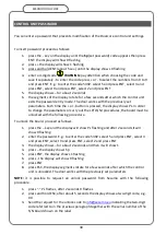
Page 30: ...der to change the parameters or carry out the LP LS Sd procedures the board must be unlocked with the following procedure To unlock the board proceed as follows 1 press the key and the display will show Ps flashing and after 2 seconds it will show 0 flashing 2 enter the password E g to enter the code 5392 select 5 and press ENT select 3 and press ENT select 9 and press ENT select 2 and press ENT 3...

Page 31: ...essing ESC again Parameter Description 0 firmware version of the user controller e g 2 00 1 firmware version of the safety controller e g 2 00 2 type of automated system C0 C1 see table below 3 total weight of the moving mass P0 0 100kg P1 100 200kg P2 200 300kg 4 total number of operations performed by the control unit 5 sensor configuration installed refer to the S code table in the description ...

Page 32: ...y contact activated Note with RD100 automated system the opening operating mode is managed alternately by the Master control unit and the Slave control unit Closing is always managed by the Master control unit Faulty operation causes solutions Description Warning on the display Cause solution The door remains open Op Steady The logic selector is on the stop open change logic position An opening co...

Page 33: ...or or if there is something activating the sensor e g person or object in the field of action Find the cause of the problem first checking that the sensor s field of action is clear of persons or objects and that the wiring is intact and connected correctly Protection circuit errors Warning Description F8 Flashing Communication error with Safety Controller active warning only when the door is stat...

Page 34: ...g Slave board error warning active only on Master A3 Flashing Master board error warning active only on Slave A4 Flashing Battery management error A5 Flashing Mains power failure error A6 Flashing Master Slave opening sensor signal synchronization error A7 Flashing Dead battery error A1 check the wiring between MASTER and SLAVE and make sure that both boards work with the same firmware version A2 ...

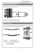
Page 35: ...vailable on request INTERLOCK CONNECTION In order to obtain the interlock function connect two automated system to each other as shown in the figure below The interlock function allows the movement of only one automated system at a time The interlock function cannot be used on RD100 A MASTER parameter settings 15 1 17 1 B SLAVE parameter settings 15 2 17 1 C BIPOLAR SWITCH not supplied recommended...

Page 36: ...lector if this has been installed Close the cover of the automated system following the reverse procedure used to remove it Make sure that the two fixing screws of the cover are well tightened Before finishing the installation of the automated system remember to apply the stickers with the signs provided on the sliding doors Give the customer the technical documentation of the product in particula...

Page 37: ...d selector will remain positioned in the logic preceding the lack of mains At this point the automated system is ready to operate in ways that depend on the type of peripheral devices and accessories installed and on the logic selected by means of the selector it will perform automatic opening and closing of the window so as to allow the passage of people in complete safety and continuously The op...

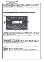
Page 38: ...ming the acquisition 2 Entry and Exit the door operates in entry and exit mode If installed the electric lock does not block the doors 3 Exit Only the door operates only in exit mode If installed the electric lock locks the doors every time they arrive in the closed position 4 Reduced opening the door operates in reduced opening mode The factory setting corresponds to 50 of the passageway a value ...

Page 39: ...me they arrive in the closed position 5 Entry and Exit the door operates in entry and exit mode If installed the electric lock does not block the doors PR Opening button controls the opening of the door in the second function it can be used by technical personnel for parameter adjustments ESC Manual opening the door works only by using the PR button in the second function it can be used by technic...

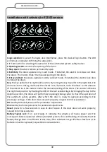
Page 40: ...e absence of the electric lock the motors hinder the manual opening of the doors The selector indicates the night lock position by flashing the LED of the last selected logic By bringing the key to the daytime position the doors will perform two opening closing cycles to check the operation of the automatic safety systems after which the door is ready to operate according to the previously set log...

Page 41: ...ning of the doors Each time the electronic key is inserted the automated system switches from normal operating condition to locking condition in closing mode and vice versa During the transition from locked to normal operation the leaves perform a complete opening and closing maneuver in order to allow a person to enter Operation in the absence of mains with batteries installed Panic mode when the...

Page 42: ...y an authorized technician Disconnect the mains power supply using the bipolar switch upstream of the automated system Open the automated system by removing the cover Disconnect the batteries Check the tightness of the screws of the carriages and of the components installed inside the box Check the wiring connections between the accessories the sensors and the electronic control unit Clean the sli...

Page 43: ...rect selection of the operating logics Check the efficiency of the batteries by making the system operate temporarily in the absence of mains power Test the correct operation of the panic closing down if installed PARTS REPLACEMENT For the RD100 version it is necessary to proceed with the preventive replacement of the following components according to the number of opening closing cycles detectabl...

Page 44: ...44 SESAMO DUALCORE Fig A Fig B ...

Page 45: ...45 SESAMO DUALCORE Fig 1 ...

Page 46: ...46 SESAMO DUALCORE Fig 2 ...

Page 47: ...47 SESAMO DUALCORE Fig 3 ...

Page 48: ...48 SESAMO DUALCORE WARNING Exit way ONLY for RD100 Fig 4 ...

Page 49: ...49 SESAMO DUALCORE Fig 5 ...

Page 50: ...50 SESAMO DUALCORE Fig 5 A ...

Page 51: ...51 SESAMO DUALCORE Fig 6 Fig 7 ...

Page 52: ...52 SESAMO DUALCORE Fig 8 Fig 9 ...

Page 53: ...53 SESAMO DUALCORE Fig 9a Fig 10 ...

Page 54: ...54 SESAMO DUALCORE Fig 11 Fig 12 ...

Page 55: ...55 SESAMO DUALCORE Fig 13 Fig 14 Fig 15 ...

Page 56: ...56 SESAMO DUALCORE Fig 16 Fig 16a ...

Page 57: ...57 SESAMO DUALCORE Fig 17 Fig 17a ...

Page 58: ...58 SESAMO DUALCORE Fig 18 Fig 19 Fig 20 ...

Page 59: ...59 SESAMO DUALCORE Fig 21 Fuses 6 3A T J ...

Page 60: ...60 SESAMO DUALCORE Fig 22 ...

Page 61: ...61 SESAMO DUALCORE Fig 23 1 Fig 23 2 ...

Page 62: ...62 SESAMO DUALCORE Fig 24 PARAMETER 30 1 ...

Page 63: ...63 SESAMO DUALCORE Fig 25 PARAMETER 30 1 Exit way ...

Page 64: ...64 SESAMO DUALCORE Fig 25 A ...

Page 65: ...65 SESAMO DUALCORE Fig 26 ...

Page 66: ...66 SESAMO DUALCORE Fig 27 PARAMETER 31 1 ...

Page 67: ...67 SESAMO DUALCORE Fig 28 PARAMETER 31 0 ...

Page 68: ...68 SESAMO DUALCORE Fig 29 ...

Page 69: ...69 SESAMO DUALCORE Fig 30 Fig 31 ...

Page 70: ...70 SESAMO DUALCORE Fig 32 Standard LH100 LH140 Parameter 13 1 Fail safe LH100 LH140 Parameter 13 2 Bistable LH100 Parameter 13 3 LH140 Parameter 13 3 RD100 Parameter 13 4 ...

Page 71: ...71 SESAMO DUALCORE Fig 33 ...

Page 72: ...72 SESAMO DUALCORE Fig 34 ...

Page 73: ...73 SESAMO DUALCORE SESAMO srl Str Gabannone 8 10 15030 Terruggia AL Italy Tel 39 0142 403223 Fax 39 0142 403256 www sesamo eu e mail info sesamo eu C187290_00 ...

Reviews: