MX-7000 Installation and operation manual
P a g e
| 14
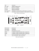
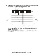
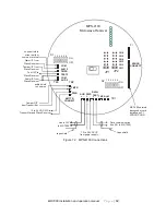
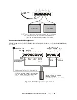
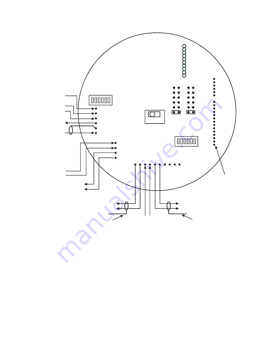
Figure 12 MPS-4100 Connections
TB1
TB2
TB3
S2
+ - + - + -
AUD PWR
DATA/
TEST
TMP ALM
XMTTR
CONNECT
TMPR
-
+
PWR
COM
ALM 2
TMPR
TEST 2
COM
AUD 2
CH6
CH5
CH4
CH3
CH2
CH1
XPNDR
CONNECT
Audio O/P
to MX-7000
Tamper O/P
from Transmitter
tape shield
JP1
JP2
S1
1 2 3 4 5 6
ON
OFF
1 2 3 4 5 6
ON
OFF
12 to 24 VDC O/P to
Transmitter and Slave Receiver
12 to 24 VDC I/P
from power supply
MPS-4100
Microwave Receiver
Alarm I/P from
Slave Receiver
Tamper I/P from
Slave Receiver
Audio I/P from
Slave Receiver
audio shield
to common
MX-7000 network
transponder card
installed on PI
XPNDR CONN
P1
Data communication
bus (I/O to MX-7000)
tape shield
connect return
wires to either
common terminal
Test O/P to
Slave Receiver


