MX-7000 Installation and operation manual
P a g e
| 12
•
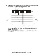
Set the transmit and receive address for each processor on the transponder PCB. Refer to Figure
24 or the FPS processor installation manual for address switch settings.
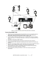
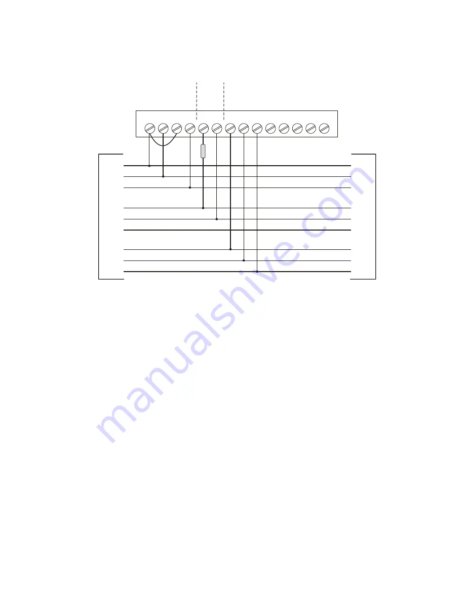
Figure 10 FPS Processor Wiring Connections
NOTE 1: Tie shields as shown. Never tie audio, data and power shields together. Make sure no
shields are shorted or grounded.
Determine value of resistor R1 (if required) individually for each processor. See Appendix A for
additional information.
1
2
3
4
5
6
7
8
10
11
12
13
14
9
AUDIO
12 - 16
VDC
DATA
1
2
co
m
m
o
n
+
_
sh
ie
ld
+
_
R1
sh
ie
ld
1
C
shield
+
_
shield
+
_
shield
A
U
D
I
O
P
O
W
E
R
D
A
T
A
from previous
processor
or MX-7000
to next
processor
or MX-7000
1
C
shield
+
_
shield
+
_
shield
A
U
D
I
O
P
O
W
E
R
D
A
T
A
NOTE 1
NOTE 1
NOTE 1
TB1


