MX-7000 Installation and operation manual
P a g e
| 31
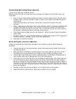
Connecting and testing the processors
Connect the processors to the MX as follows:
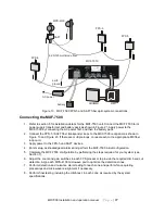
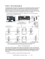
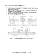
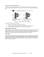
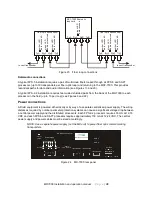
Refer to Figure 22 for FPS 2-2 copper wire loop connections and Figure 23 for FPS-5 fiber optic loop
connections.
•
FPS 2-2: Using 18 AWG twisted shielded pair cable connect the data terminals of the MX-7000
multiplex copper loop card, terminals 1 (data+), 2 (data-), and 3 (shield) to the data terminals of
the processor.
Connect the audio bus wires for loop 1 to terminals 1 audio and 2 common of the audio
connector.
•
FPS 5: Using approved Fiber Optic cable, connect the fiber loop ST connectors to the MXF-7500
multiplex fiber loop card. Typically, Tx A and Rx A on the loop card connect to Rx B and Tx B
respectively on the first processor on the loop. Then, Tx B and Rx B on the loop card connect to
Rx A and Tx A at the last processor on the loop (see Figure 23).
•
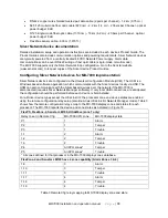
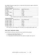
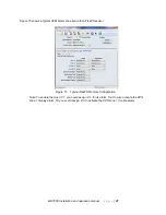
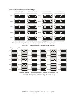
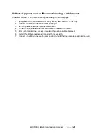
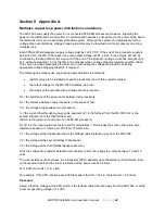
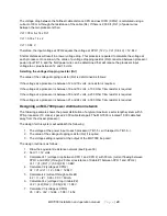
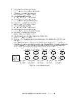
Verify that the correct address is set on each processor. Refer to Figures 25 and 26 for address
switch setting.
•
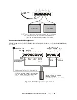
As shown in Figure 21, connect the MX transformer to the MX-7000. Apply 24 VAC by plugging in
the MX transformer. If available, connect the 24 VDC battery pack.
•
Apply power to the field processors.
Bench testing the processor addresses
Senstar recommends bench testing each processor on its multiplex loop before field-installing the
equipment:
•
Connect a processor to its designated loop card and then apply power to the MX-7000 and the
connected processor.
•
Make sure there are MX display zones assigned for this loop processor’s zones. See Section 7
for setting the loop, transponder type and number and zone number to MX display zones.
•
If the processor and transponder card are operating properly, the MX display zones assigned to
this processor will be secure (steady green), not in communication fail.
•
If the zones are in communication fail, verify the address switch settings on the transponder card,
and check the power supply voltage and your connections. If the problem still exists, swap the
processor’s transponder card with another transponder card that has the same switch settings. If
the problem continues, replace the processor with another. If the problem still exists, and there is
more than one loop card, try another loop card. If the problem remains, contact Senstar Customer
Service for assistance.
•
Simulate an alarm and a tamper condition on one or both zones to verify operation.
•
Repeat the tests for each processor, and for each multiplex loop in the system.

