MX-7000 Installation and operation manual
P a g e
| 7
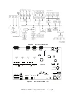
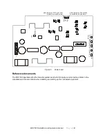
LED
Description
LED 1 - D24
Steady when system is ready
D1 - LINK
Ethernet communications
D2 - 100
Ethernet communications
D3 - DUP
Ethernet communications
D4 - COL
Ethernet communications
D6 - Processor OK
LED steady on o/s load, pulsates to indicate that the o/s is operating
D17 - Status
LED steady on application load, flashes to indicate application is operating
Table 1 Main board LED descriptions
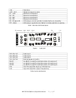
Figure 4
Audio card
TB1 Pins 1 & 2
Audio input 1
TB1 Pins 3 & 4
Audio input 2
TB1 Pins 5 & 6
Audio input 3
TB1 Pins 7 & 8
External speaker connection
GAIN 1
use GAIN 1 to adjust the input signal volume for audio input 1
GAIN 2
use GAIN 2 to adjust the input signal volume for audio input 2
GAIN 3
use GAIN 3 to adjust the input signal volume for audio input 3
TFA
Use TFA to adjust the frequency of the alert tone
TLS
Use TLS to adjust the volume of the alert tone
Table 2 Audio card features
1
2
3
4
1
2
3
4
5
6
7
8
J
P
1
A
B
P
1
S
P
K
P
2
G
A
IN
1
G
A
IN
2
G
A
IN
3
T
F
A
T
L
S
T
B
1
TB1 connections
GAIN 1 GAIN 2
GAIN 3
TFA
TLS


