MX-7000 Installation and operation manual
P a g e
| 30
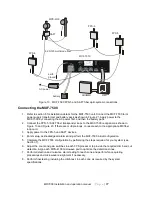
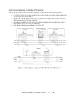
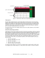
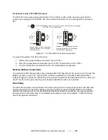
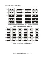
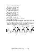
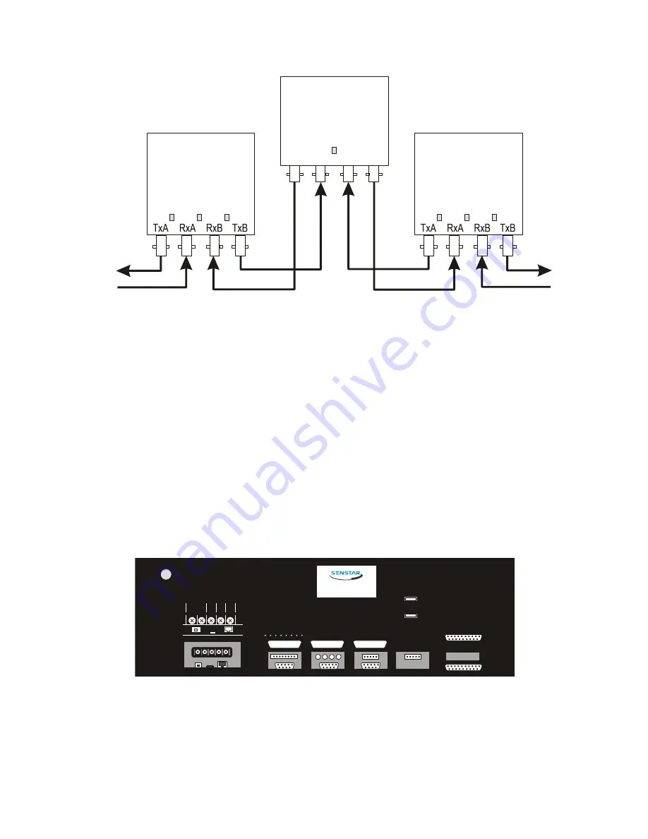
Figure 23 Fiber loop connections
Data/audio connections
A typical FPS-5 installation requires a pair of multimode fibers looped through all FPS-5 and SAFT
processors (up to 30 transponders per fiber optic loop) and returning to the MXF-7500. This provides
redundant paths for data and audio information (see Figures 13 and 23).
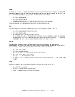
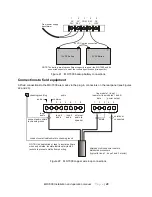
A typical FPS-2-2 installation requires two twisted shielded pairs from the back of the MX-7000 to each
processor in the field (up to 10 per loop) (see Figures 6 and 22).
Power connections
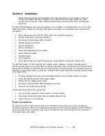
All field equipment is powered either locally or by way of a separate centralized power supply. The wiring
distances required by outdoor perimeter protection systems can cause a significant voltage drop between
a central power supply and the distributed processors. Each FPS-2-2 processor requires 30 mA at 12-16
VDC and each FPS-5 and SAFT processor requires approximately 130 mA at 12-24 VDC. The central
power supply and power cables must be sized accordingly.
NOTE: Use a separate power supply (not the MX unit) to power fiber optic communicating
transponders.
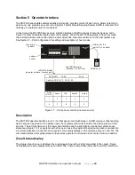
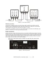
Figure 24 MX-7000 rear panel
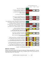
MXF-7500 fiber optic
loop card
g
re
e
n
L
E
D
d
a
ta
r
e
c
e
iv
e
d
TxA
RxA
RxB
TxB
fiber optic transponder
g
re
e
n
L
E
D
a
d
d
re
s
s
r
e
c
e
iv
e
d
a
m
b
e
r
L
E
D
d
a
ta
r
e
c
e
iv
e
d
A
a
m
b
e
r
L
E
D
d
a
ta
r
e
c
e
iv
e
d
B
fiber optic transponder
g
re
e
n
L
E
D
a
d
d
re
s
s
r
e
c
e
iv
e
d
a
m
b
e
r
L
E
D
d
a
ta
r
e
c
e
iv
e
d
A
a
m
b
e
r
L
E
D
d
a
ta
r
e
c
e
iv
e
d
B
to next transponder
to next transponder
MX-7000 Control center
line module 1 line module 2
line module 3
audio
1 2 3 4 5 6 7 8
RS-232-1
RS-232-2
RS-232-3
USB 4
USB 3
Aux Bus
line module 4
Printer
Power Supply
Xformer
24VAC
G
N
D
B
tr
y
+
1
5
V
D
C
Ethernet
Reset Switch
LED 1
MX-7000 Control center
Chassis
ground

