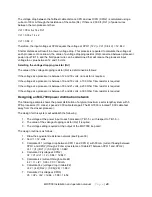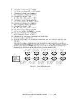
MX-7000 Installation and operation manual
P a g e
| 29
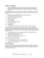
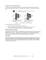
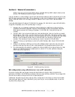
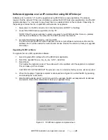
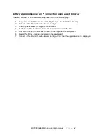
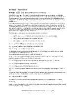
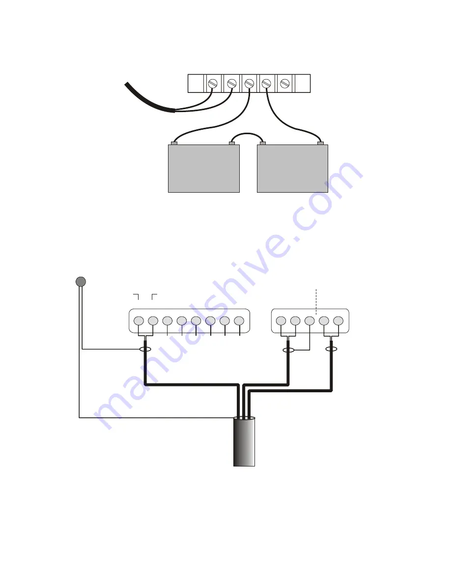
Figure 21 MX-7000 backup battery connections
Connections to field equipment
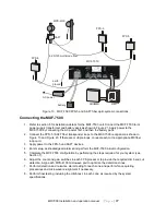
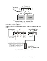
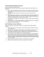
All field connections to the MX-7000 are made via the plug-in connectors on the rear panel (see Figures
22 and 23).
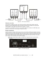
Figure 22 MX-7000 copper wire loop connections
From power supply
transformer
1
AC
28V
2
AC
28V
3
COM
4
BAT
+
5
DC
15V
+
12 VDC Battery
+
-
12 VDC Battery
+
-
24 VDC series connection
NOTE: The battery must have sufficient capacity to power the MX-7000 and its
connected sensors to meet the runtime specification (
.
site-specific)
chassis ground lug
loop 1
audio
loop 2
audio
loop 3
audio
external
audio to
speaker
connect overall cable shield to chassis ground
connect audio shield
to chassis ground
+
_
_
+
shield not
connected
shield
1
2
3
4
5
6
7
8
1
2
3
4
5
data
power output
shielded multi conductor cable to
distributed processors
(typical for loop 1, loops 2 and 3 similar)
NOTE: Use heatshrink or tape to insulate all bare
wires and shields. Insulate individual mylar/foil
jackets to prevent shields from shorting.
line module 1 (loop 1)
audio
(same for line modules 1 and 2)
audio +
common
+
c
+
c
+
c

