MX-7000 Installation and operation manual
P a g e
| 17
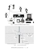
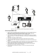
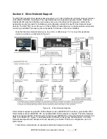
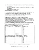
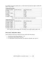
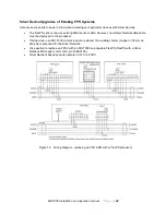
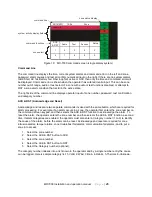
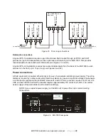
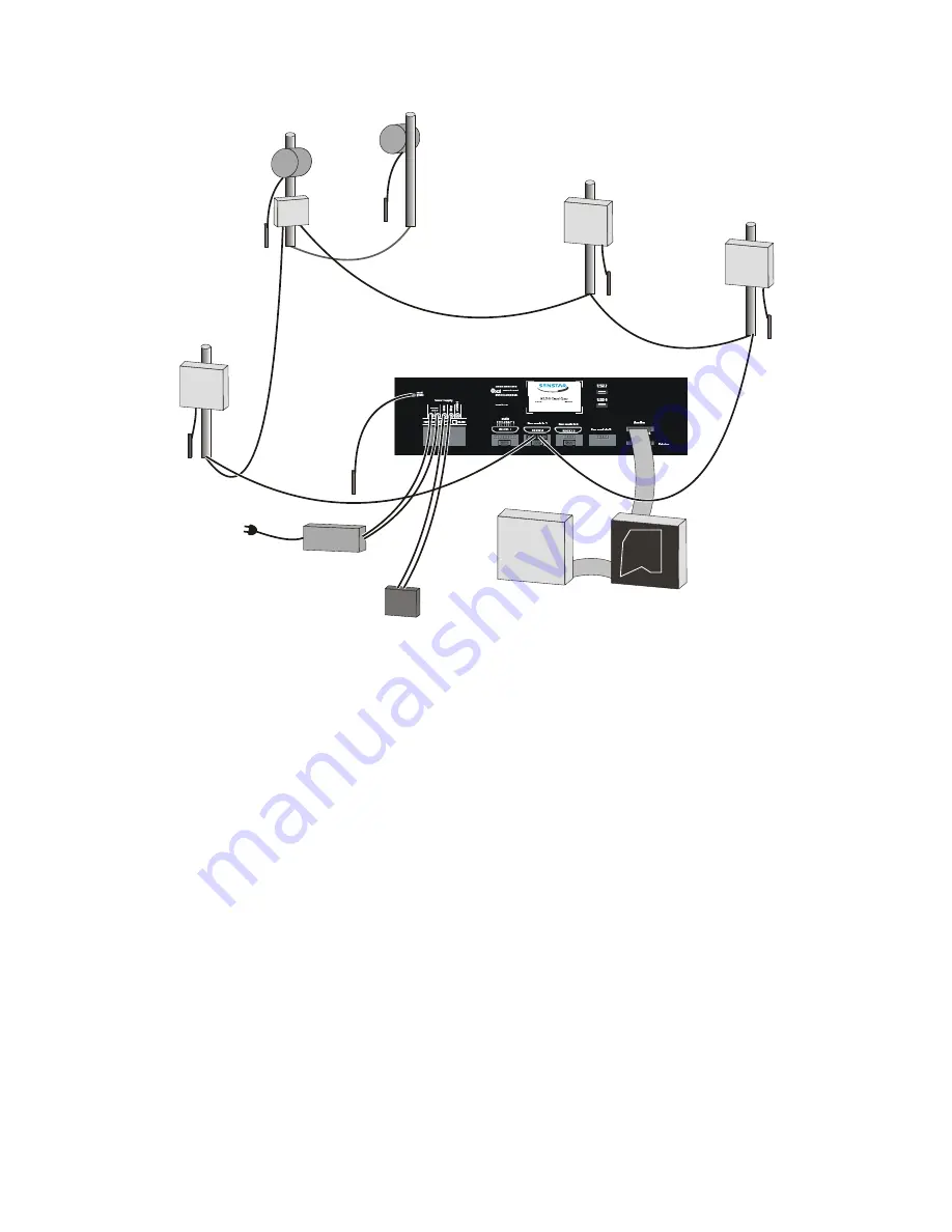
Figure 13 MXF-7500 FPS-5 and SAFT fiber optic system connections
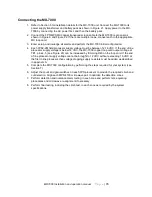
Connecting the MXF-7500
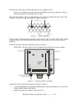
1. Refer to section 6 for installation details for the MXF-7500 unit. Connect the MXF-7500 to its
power supply transformer and battery pack as shown in Figure 21. Apply power to the
MXF-7500 by connecting the AC power first, and then the battery pack.
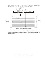
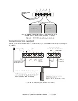
2. Connect the FPS-5 / SAFT fiber transponder loops to the MXF-7500 rear panel as shown in
Figure 13 and Figure 23. If there are multiple loops, connect each to the appropriate MX fiber
loop card.
3. Apply power to the FPS-5 and SAFT devices.
4. Enter setup, acknowledge all alarms and perform the MXF-7500 initial configuration.
5. Complete the MXF-7500 configuration by performing the steps required for your system (see
Section 7).
6. Adjust the count and gain switches in each FPS processor to provide the required climb and cut
detection. Align each MPS-4100 microwave pair to optimize the detection zones.
7. Perform detection and nuisance alarm testing for each zone and perform fence quieting
procedures and microwave re-alignment if necessary.
8. Perform final testing, including the climb test, in each zone as required by the system
specifications.
MPS-4100
MXF-7500
AC power
battery
ARI/MMI
RMI
earth
ground
FPS-5
FPS-5
SAFT
FPS-5
62.5/125 multimode fiber


