Sensory Analytics Specmetrix SA Installation & Operation Manual Download Page 46

46 | 

P a g e 


R e v 5 - 1 9 


2.


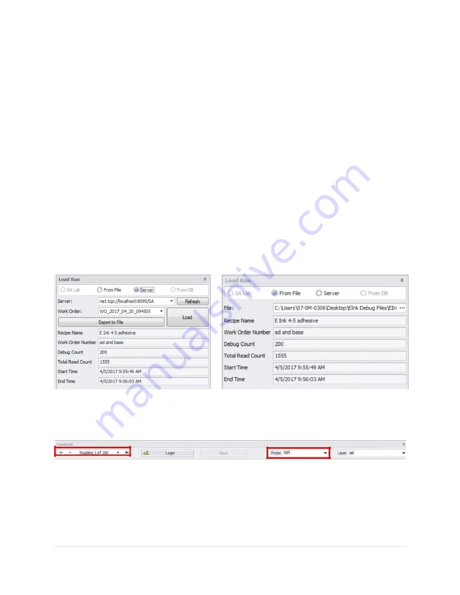
Select the option of “From File” if you are working with an exported debug zip file 

a.


Click on the ellipse “…” button to open the file selection window 


b.


Navigate to the folder and select the file to analyze 

3.


Select the option “From DB” if you wish to work with the SA Database 


a.


DO NOT Use this option if you are working directly with the SA database. Only use if you 

have copied (NOT ‘CUT’) the database to a remote location from the original. 


b.


Click “Change DB” if you have an archived database you wish to work with. Navigate to 

the folder and select the SA database (*.mdf) to work with. 


c.


The drop-down window will display the list of Work Order numbers for each run 


d.


When working with the DB, the details will be displayed below the “Load” button 


e.


If Debug Readings = 0, then there are no debug records for the given run there will 

be no readings in which to analyze. Select a different Work order number. 


4.


SA Lab will be explained in the SA Lab Manual. 


Regardless of which option, once you have selected a debug set, click the “Load” button. Within a few 

seconds, the spectral data should be displayed in the graphs. If you do not see any graphs, then make 

sure you have selected the correct “Probe” and “Layer” (top of the screen). 

Controls


From left to right: 

Reading Navigator: Using the navigation arrows on each side of the reading navigator to see the 

different debug readings. You can go backward and forwards or enter the number of the reading 

directly. 

Language: Displays a selection window to change the language without having to exit 

Summary of Contents for Specmetrix SA

Page 1: ...SA Traversing In line Coating Thickness Measurement System Installation Operation Manual The Sensory Building 405 Pomona Drive Greensboro NC 27407 USA 1 336 315 6090 www specmetrix com ...

Page 2: ...r Detection Setup 11 Network and Machine Communications 11 Emergency Stop 11 System Start Up Procedure 12 System Shut down Procedure 13 Signing On 14 SA Services 14 Change User 14 SA UI Configuration 15 ColorBands 15 CrossWeb 15 CrossWeb Line Count 15 Default User 15 Default Password 15 Default User Id 15 Inline 16 Cross web Position Update Rate 16 Decimal Places 16 Downweb Graph Count 16 Graph Co...

Page 3: ...18 SA ACS 18 SA Blown Film Settings 18 SA Inline Fixed Differential 18 Show Base Value 18 Show Total Value 18 SA Menu 18 Menu Scaling 18 Shutdown Method 18 SA Offline DFT QA 18 SA PLC Traverse Settings 18 Pic Traverse User Options 18 Fixed Width Lane Width 18 Left Right Web Percentage 19 Constant Lane Count 19 Relative Distance Unit 19 Web Division Type 19 SA Sheet Type Settings 19 SpecMetrix SA D...

Page 4: ...t 25 Lanes SpecMetrix Traversing Only 31 Adding Editing a Lane Definition 32 Users 34 User Permission levels and their privileges 34 Plants 35 SpecMetrix SA Inline Measurements 37 Main User Interface 37 Adjustable Target Set 38 Statistics Tab 38 Distance to Target 38 Debug 39 User Interface Tabs 40 Thickness Graph 40 Average Reads 40 Thickness Data 41 Historical 41 Traversing 42 Cross Web 42 Lane ...

Page 5: ... Tool 56 WHAT TO CHANGE AND HOW IT AFFECTS YOUR READING 56 Peak Tolerance 56 Fringe Variance 56 Height Threshold 56 Custom Smoothing 57 Momentum 57 Waveform Type 57 Starting Ending Wavelength 57 Index of Refraction 57 Min Max Thickness 57 Target Spec 57 Tolerance 57 SpecMetrix On Line Support 58 Other SA Menu Buttons 59 System Maintenance 60 Suggested Cleaning Interval 60 Maintenance Procedures fo...

Page 6: ...6 P a g e R e v 5 1 9 General Maintenance Checklist 62 Calibration 62 ...

Page 7: ...g to evaluate the coating thickness measurement in microns When measuring wet coatings the dry coat weight in units such as MgSI Mg4SI lbs ream or GSM is then calculated from the wet or dry thickness using data from the coating manufacturer such as wet density lbs gallon or gram liter and solids by weight and solids by volume Product Safety Before using your SpecMetrix System Your SpecMetrix Syste...

Page 8: ...dicated Circuit Single Phase with neutral and ground 50 60Hz 120 240VAC 15Amp Circuit min 14AWG 1 63mm diameter wire SpecMetrix ICU can be hard wired to the main power input or a wall socket Primary Operator Workstation will require one or two wall sockets depending on the configuration that must be in the same dedicated circuit All Ethernet cables must be minimum CAT 6 Shielded ICU can be maximum...

Page 9: ...mains supply adjacent to the Display Unit and the In line Control Unit This means a direct connection back to the fuse Unit The instrumentation should not be spurred off a thyristor controlled heater or motor due to the electrical interference this would cause The Control Unit and Display Unit can be run on the same 15 amp circuit The Display Unit requires a standard 120VAC 240VAC receptacle the C...

Page 10: ...from the Control Unit to the customer s network if external data storage is required Must use minimum CAT 6 Shielded Cable SA will supply install and terminate the Ethernet cable unless agreed otherwise with plant personnel The probes are optical devices with no electrical connections and so can be mounted in an explosive environment The Control Unit however contains electrical components and is n...

Page 11: ...for any user account that will be given access to the SpecMetrix Display Unit is to have local admin access as well as proper access to read write to any network path that is defined as a file repository It is permitted and recommended to use file mapping to network paths For the main electrical cable run a properly terminated Line Neutral and Ground power cable to the side of the ICU to the clams...

Page 12: ...lectrical cabinet to the ON position The green light on the front should illuminate Wait a minute for the background services to start Then press the SA service red tile The screen will gray out while starting the service Once the SA service tile goes green the system is ready to use ...

Page 13: ... green SA Service Tile Then Select Yes to properly shut down the SA service Select the red Windows Shutdown tile This will start the computer shutdown process Then select Yes to shut down the computer Turn the Disconnect to the OFF position to power down the ICU ...

Page 14: ... Green Color If Server Status is Stopped Red Color click the Server Status Tile once Change User By Default SA will be logged in as a Base Level User named Default This allows for limited view only rights into SA To log in as a different user click on the Change User Tile You will see a popup window appear in the upper left corner of the screen for you to enter your credentials There are five diff...

Page 15: ...e by side in multi line systems In most cases values can be changed by clicking on the value field until the desired setting appears Select the SAVE button to save any changes made Requires Local Admin Access or higher ColorBands Percentage of the graph the at the band occupies By default GREEN 50 YELLOW 25 RED 25 CrossWeb CrossWeb Line Count Number of Cross Lines to display Default User Default P...

Page 16: ...he graph to respectively draw across very slowly Max 3600 1 hour of date for single probe Graph Configs Cross Web Die Down Web Lanes Polar Configuration options Display Thickness on Bar Graph Display the thickness of the region inside the Bar on the graph Invert Crossweb Graph This will flip the graph on its x axis Options are True or False Smooth Setting this to True will apply a smoothing algori...

Page 17: ...oes not pertain to the Traversing System Status Display Type Configuration options for Cross Web Traverse Left side Name A label for the left side of traversing sides Traverse Right side Name A label for the right side of traversing sides Logging Logging Interface Set condition levels for the following Logging Interface Data Service Database Call I O Board I O Boards Line Controller Motion OPC PLC...

Page 18: ...ne Fixed Differential Show Base Value Shows the Base Value in probe control Show Total Value Shows the Total Value in probe control SA Menu Menu Scaling Changes the scale size of the SA Menu Tiles Shutdown Method Shutdown method when System Shutdown button is selected from SA Menu SA Offline DFT QA This portion of the config file does not pertain to the Traversing System SA PLC Traverse Settings P...

Page 19: ... of lanes Unless the number of divisions is less than 1 inch 25mm widths Relative Distance Unit Distance Units for setting Fixed Width Length Web Division Type Left Center Right Segments Left and Right side of the detected web by Web Percentage with a remaining percentage for the center Fixed Width Once the Web Width is determined the web will be divided equidistantly on the Lane Width distance SA...

Page 20: ... Add and edit recipes User security Lane and Plant configurations Function access will vary depending on User Access Level The SA Data Manager interface allows you to Add Edit recipes setup lane definitions for traversing systems User security and the Plant Database ...

Page 21: ...ger UI is currently active the status will change from Running to Stopped and likewise will change from Stopped to Running once the service is restored Database transactions Save Delete cannot take place when the service is Stopped New Group Each Module can add a NEW item or Edit an existing item The item shown depends on what is selected in the Navigation Region at the bottom of the page It may b...

Page 22: ...screen to allow for full visibility of all recipe data by hiding filter panel on the left Filter Region Filtering mechanism to see recipes in groups filters This allows a plant to enter an string in the filter text field which in turn gets rendered as a selectable filter Clicking on the filter will change the recipe Selection region to display only the associated recipes with that filter Next to e...

Page 23: ...le layers defined a user can review the layers by selecting the layer within the drop down Module Navigation Region To navigate and view different modules mouse over and click on the module name When you mouse over the module name will change color to indicate the selection If the login is changed the screen will automatically reset to the Recipes module What options are available can vary dependi...

Page 24: ...mation on this screen and while all of it may be relevant to your needs not all of it is required For fields that are required or that have dependency properties has validation that takes place when an attempt is made to save the recipe If not all the required information is entered an appropriate alert will be displayed as Red circle with X or Yellow caution with Hovering over the icon will descr...

Page 25: ...nutes for a given coating By answering a few questions the Recipe Assistant will generate a very good baseline recipe which will be sufficient for most coating combinations There will still be room for further optimization as needed to dial in the recipe for final optimization Getting Started with the Recipe Assistant Once the user is in the editor the Recipe Assistant Button will be displayed in ...

Page 26: ...ils or coat weight units such as mg in2 mg 4in2 g m2 lbs ream etc Sensor Type NIR or VIS The recipe wizard directs its results to one or the other detector sensor Measurement State This determines whether the coating is being measured in the wet state or dry state Output State How does the user want the results converted for output Wet or Dry Also used as dry Basecoat If this recipe will be used a...

Page 27: ...imary layer being measured If none of these are applicable for the specific coating the closest option should be chosen Clear Top Coat Group box This is a Top Coat This is asking if the layer being defined is a top coat being applied over the top of another layer of coating for example base coat If Yes then put a check mark in this box and proceed to answer the Base Opacity Base Opacity There are ...

Page 28: ...coating supplier It is important to understand that of solids by volume is required only for measuring dry coating in coating weight units and not coating thickness units It is not required either while measuring wet coatings or while measuring the coating in the units of thickness such as microns Layer Coating Name this is a required field This prints on reports graphs and is part of the selectio...

Page 29: ... has been split out from a single value to a range and a range The range allowance is dependent on the target spec For any Target Spec whose calculated conversion is greater than 7 µm the allowable range is 50 of the target spec in either direction If the conversion is less than or equal to 7 µm then the Low range allows a value which will set the Low Spec Limit at the sensor minimum and a High ra...

Page 30: ...r click on Finish to finalize and generate the new recipe Once the user clicks on Finish the Recipe Assistant will close and the Editor will now be populated with the data based on what you put into the Assistant IMPORTANT NOTE You must tap Save before exiting the editor else all data entered will be discarded ...

Page 31: ...ipe editor there is a filter section However the filter only separates out based on plants as of the current release The Selection grid functions the same as the Recipe module The Detail view shows the pertinent information regarding the currently selected Lane Definition ...

Page 32: ...termine if the edge is moving With PLC Traversing the edge is detected with each pass using Photo Eyes mounted to left and right of the probe Lane Count This is how many divided lanes the user wishes to separate out the material into It is required that 100 of the web width be accounted for and therefore represented Changing this value will automatically calculate divided lanes into equidistant le...

Page 33: ...h is defined as Pause Positions in the Lane Definition of the Data Manager The pause position forces the probe head to pause at specific points on the web relative to the detected web edge To add a pause position type in the distance from the edge of the web specifically the edge that is closest to the SpecMetrix Traversing Home position in the Add Pause field and click the symbol at the end of th...

Page 34: ...ss level has permission to add new recipes lanes They can also edit recipes provided the minimum access level for the recipe is set to Supervisor Supervisor level can add remove user supervisor level users to the User Security These users have visibility to Recipes Lanes Users modules Local Admin This is the highest level of access for a defined Plant This access level can add edit recipes provide...

Page 35: ...anes This level of access does however possess the ability to add modify remove ANY user regardless of the assignedPlant Support This level of access is strictly limited Sensory Analytics Technical personnel Note Login name is a unique field If a login name already exists on the system regardless of visibility in the editor then you will need to select a different name as there cannot be 2 logins ...

Page 36: ...o perform scripts for updates or maintenance Lastly the plant client must be able to maintain 100 up time of the server for any SpecMetrix unit that will be accessing it during production this means using the In line function It is the responsibility of the plant to ensure that all connections and network settings are properly configured and accessible for all users who access and use a SpecMetrix...

Page 37: ...iate sensor This means that each recipe is set up to work for a specific sensor Recipes are created edited and deleted in the SA Data Manager see the previous section 2 Basecoat Drop down items are generated when Also used as dry Basecoat option is checked on the Recipe Assistant s General Information page 3 Work Order This field populates itself automatically when the measurement process starts u...

Page 38: ...inal graph on Right side small image the new graph on the left shown in In line Not all recipes qualify as Adjustable Target Spec recipes The recipe must be a simple single layer recipe not defined as basecoat or subtractive and cannot be set if used in a differential system Statistics Tab The Statistics tab is dynamic and if the system uses fixed probes then each probe will be displayed with the ...

Page 39: ... measurement readings in our Analysis Tool You will want to create a debug file to load into the Analysis Tool To do this you open your Inline panel and select the Debug tick box closest to the Reflectance bar of the probe you want to take debug readings of This will collect detailed information of the next 100 readings made by your probe and then it will fall out of debug This means the box will ...

Page 40: ... once every probe cycle Default 1 0 second Thickness Graph Tab Average Reads Displays the Moving Average the average value for measurements taken over a certain period or the Full Run Average the average value for measurements taken from the beginning of the probe cycle This will hold an average of the last five probe cycle readings that had a yielded value greater than 0 0 Average Reads Tab ...

Page 41: ...of all measurements taken during the probe cycle 4 Standard Deviation A measure of the amount of variation from the Target Specification taken during the probe cycle 5 Distance to Target The distance or from the average to the Target Specification as defined in the recipe Historical Quick reference to view general run occurrences with the ability to select run for manual CSV output as well as sele...

Page 42: ... which graphs each independent reading based on a running smoothing average The graph is updated once per probe cycle with all independent location evaluations The cross web points are plotted individually based on location and are not removed based on probe cycle evaluation ...

Page 43: ... to yield a single lane average Each change of direction the traverse head makes will reset the current traverse calculation as the probe moves across the web If the probe is stopped in a lane the data will be recorded as a single value regardless of how long the probe is motionless Die Graph This represents the total width of the machine roller which is divided into a predetermined number of regi...

Page 44: ...t range Starting from the top the colors are Amber Blue Green and Red Green Only Measurement is within range Blue Amber PLC Only Measurement has moved slightly high of the range Blue Only Measurement has moved far high of the range Red Amber PLC Only Measurement has moved slightly low of range Red Only Measurement has moved far low ofrange Amber light used in PLC Traversing only In SA Traversing o...

Page 45: ...g purged Because of database size restrictions Sensory Analytics cannot guarantee data to remain in the system for longer than seven days Logging Inline Graph Like all other SA utilities Analysis Tool requires different credentials to accomplish certain things In this case the only difference between a user level and administrative level is the ability to save changes to the recipe within the Anal...

Page 46: ...for eachrun d When working with the DB the details will be displayed below the Load button e If Debug Readings 0 then there are no debug records for the given run there will be no readings in which to analyze Select a different Work ordernumber 4 SA Lab will be explained in the SA Lab Manual Regardless of which option once you have selected a debug set click the Load button Within a few seconds th...

Page 47: ...ght peaks within the Min Max evaluation range On a scale of 0 0 to 1 0 0 to 100 the y axis of this graph shows the normalized probability of the thickness weight for the particular measurement Unless measuring a multi layer material there should only be one obvious peak Multiple peaks usually occur when there are multiple layers or when there is noise present in the light signal This optical noise...

Page 48: ...ight side of the Normalized Data Window Info Integration Time IT time in milliseconds used to sample the optical package detector array once Saturation Percentage of reflectance Reflectance Flag The percentage of saturation It will either be Low Normal or High Thickness µm The thickness of the material shown in microns Converted Thickness The thickness of the material converted into another unit o...

Page 49: ...ess estimate Subtractive Amount Only shows information if a Differential configuration is being used This will show the thickness of the applied coating Peaks The data for each of the peak points of the Normalized Graph separated by top points and bottom points The following image contains data for wavelength height distance from one peak point to its adjacent peak to the right and thickness in mi...

Page 50: ... measured This becomes apparent inthe Spectral graph as you slide the Start or End wavelength indicator Index of Refraction IOR Changing the IOR will not change the wavelength or wave graph but will have a direct impact on the peak graph and the resulting thickness Height Height Threshold This is the minimum amount of height distance from the bottom point to the top point for a given interference ...

Page 51: ...ctive lines in the Wave Graph Normalized line Black line the normalized spectral array for the wavelengthrange Smoothing Line Green line smoothing line to improve readability of the normalized spectral array Peak Line Red line line that graphs from peak to peak that identifies valid peak ranges Peak points Red dots points that identify each peak within a range ...

Page 52: ...ll flag the measurement as a No Read The typical range for this parameter is 0 1 to 0 5 Fringe Variance This is the amount of variation allowed in thickness between the calculated thickness and individual peak estimates See Section 9 for an example of estimating thickness using peak estimate tool The default value is 0 3 Depending on the nature of the samples and the quality of interference this p...

Page 53: ...inimum and maximum range ofthickness that are evaluated during measurement Index of Refraction Changing the IOR will not change the wavelength or wave graph but will have a direct impact on the peak graph and the resulting thickness Minimum Evaluated Percent The required minimum percentage of readings that are successfully evaluated for a reading to be displayed Wavelength Range Increase or decrea...

Page 54: ...lly the Range has been split out from a single value to a range and a range The range allowance is dependent on the Target Spec For any Target Spec whose calculated conversion is greater than 7 µm the allowable range is 50 of the target spec in either direction If the conversion is less than or equal to 7 µm then the Low range allows a value which will set the Low Spec Limit at the sensor minimum ...

Page 55: ...ter investigate them NOTE the value with µ next to it is the micron thickness that is calculated If the conversion has been applied then the conversion value will be displayed in the adjacent column Above the results grid you will see what the determined success rates are along with Average microns for this set of data and the average of the calculated units displayed under Average Gravimetric Whe...

Page 56: ... 0 2 is used in this field then a 20 variation is acceptable between the calculated thickness by the software and the estimated thickness by the peak analysis If the variation is more than what is acceptable as defined by the acceptance tolerance value then the software will flag the measurement as a No Read The typical range for this parameter is 0 1 to 0 5 Fringe Variance This is the amount of v...

Page 57: ...nm and Near Infra red NIR which is from 900 nm 1700 nm When you adjust the wavelength ranges you are narrowing the available spectrum in which is measured This becomes apparent in the Wave graph as you slide the Start or End wavelength indicator Index of Refraction The Index of Refraction is the dimensionless number which describes how fast light propagates through the material Changing the IOR wi...

Page 58: ...connection establishing a remote connection with Sensory Analytics can be achieved by double clicking on the Team Viewer Support icon located on the desktop as shown below Clicking this icon will result in a pop up window opening as shown below For Sensory Analytics to provide the remote support you will need to provide the 9 digit Team Viewer ID as well as the Team Viewer password There is no way...

Page 59: ...ompt indicating this as well Depending on how you requested the system be set up with the sensory technician the system will either shut down or restart The image to below will allow users to minimize the SA Menu window and return to the Windows desktop environment without shutting down the SA software SA Config Tool Troubleshooting Tool to be used by authorized SpecMetrix Representatives only Cha...

Page 60: ... environment Maintenance Procedures for Lab and In line systems We suggest using compressed canned air for dust particle removal Never use water or liquids to clean electronic components WARNING Make sure power is turned off to electronics before performing any maintenance 1 Clean fan ports with compressed air blow outward 2 Check particle filter replace if necessary 3 Using Compressed air blow of...

Page 61: ...d look like Figure 63 Above 3 To disconnect the lamp from the system press the tab indicated by the red arrow while pulling the two ends of the quick connect away from each other in Figure 64 above 4 To install a new lamp reverse the last three steps being careful not to tighten the set screw in the aluminum housing so hard that it damages the lamp The set screw should be snug with very little tor...

Page 62: ...nspect the system for damage 8 Check all probes Lab or In line for damage 9 Clean probes if necessary 10 Clean filters 11 Check for any visual damage to cable conduit that is protecting fiber optical cables 12 Check for any heat related damage due to equipment placement near any ovens Calibration There is no requirement for calibration on individual coating standards on a daily basis A NIST tracea...

Page 63: ...ipe for the TVU TVU 4 Run the NIST recipe to make sure the values being read are within an acceptable tolerance range to the NIST traceable value shown on the TVU We trust that the above information will be sufficient to meet your training and troubleshooting needs However in the unlikely case of any difficulties encountered in the operation of the SpecMetrix software package please contact your a...

Reviews: