User Manual
130
User Manual
131
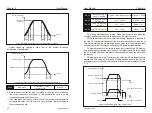
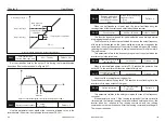
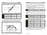
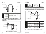
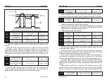
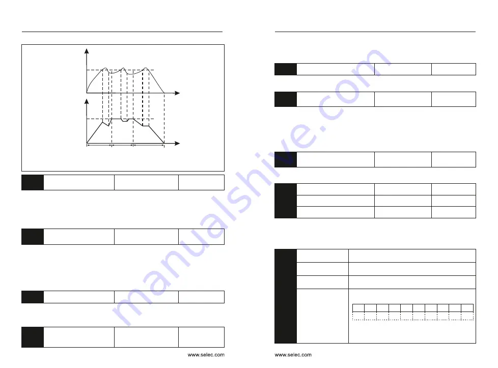
Figure 6-26 Diagram of the overcurrent stall protection function
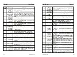
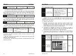
P9-07
Power-on short
circuit protection option
Default
:
1
0: Invalid
1: Valid
The inverter can be selected to detect whether the motor is shorted to
ground when it is powered on.
If this function is enabled, the UVW terminal of the inverter will have a
voltage output for a period of time after power-on.
P9-08
Brake unit action
starting voltage
200.0~2000.0V
Default
:
690
The starting voltage Vbreak of the built-in braking unit action, the setting of
this voltage value is as follows:
800 ≥ Vbreak ≥ (1.414Vs+30)
Vs- Input AC power supply voltage of the inverter Note: Improper setting of
this voltage may cause the built-in brake unit to operate abnormally!
P9-09
Number of automatic resets
0
〜
20
Default
:
0
When the inverter selects fault automatic reset, the number of automatic
resets can be set. After the number of times, the inverter outputs a fault status.
P9-10
Fault output action
selection during
automatic fault reset
0
:
No action
1: action
Default
:
0
When the fault automatic reset function is set in the inverter, the fault
output is activated during the automatic fault reset.
P9-11
Fault auto reset interval
0.1s
〜
100.0s
Default
:
1.0s
The waiting time from the inverter fault alarm to the automatic fault reset.
P9-12
Input phase loss protection
option
0: Prohibited
1: Allowed
Default
:
1
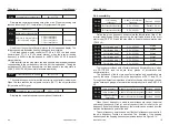
The inverter has the input phase loss protection function from the 18.5kW
G type machine and above. The power of the 18.5kW P type machine has no
input phase loss protection function regardless of whether P9-12 is set to 0
or1
Choose whether to protect the input phase loss.
P9-13
Output phase loss protection
option
0
:
Prohibited
1: allowed
Default
:
1
Choose whether to protect the output phase loss.
P9-14
First failure type
Second failure type
Third failure type (last time)
P9-15
P9-16
–
–
–
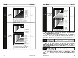
Record the last three fault types of the inverter, 0 is no fault. For the
possible causes and solutions of each fault code, please refer to Chapter 7
for related instructions.
Frequency at the
third failure
Frequency at the most recent failure
Current at the
third fault
Current at the last fault
Bus voltage at the
third fault
Bus voltage at the most recent fault
Third fault input
terminal status
The status of the digital input terminals in the
most recent fault, in the order:
BIT9 BIT8 BIT7 BIT6 BIT5 BIT4 BIT3 BIT2 BIT1 BIT0
X10
X9
X8
X7
X5
X6
X4
X3
X2
X1
When the input terminal is ON, its corresponding
secondary position is 1, and OFF is 0. The status
of all inputs is converted to decimal display.
P9-17
P9-19
P9-20
P9-18
Output current
Overcurrent stall
protective current
Output frequency
(Hz)
Set frequency
Time (t)
Acce-
leration
process
Constant
-speed
process
Deceleration
process
Time (t)
Chapter 6
Chapter 6

