


User Manual
126
User Manual
127
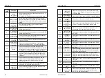
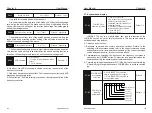
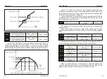
Figure 6-25 Schematic diagram of arbitrary arrival current detection
Output current
Arbitrary arrival
current
ON
OFF
Time
Arbitrary
current width
ON
ON
OFF
OFF
Timing function
selection
0: Invalid
1: Valid
Default
:
0
Timing duration
source
0
:
P8-44 1
:
AI1
2
:
AI2 3
:
AI3
Analog input range
corresponds to P8-44
Default
:
0
Timing duration
0.0Min
〜
6500.0Min
Default
:
0.0
P8-42
P8-43
P8-44
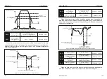
When the P8-42 timing function selection is valid, the inverter will start
timing when it starts. After the set timing running time, the inverter will
automatically stop and output the ON signal. Each time the inverter starts, it
starts from 0, and the remaining running time can be viewed through U0-20.
The scheduled running time is set by P8-43 and P8-44, and the time unit is
minute.
This group of parameters is used to complete the timing operation of the
inverter.
AI input voltage
protection value lower
limit
0.00V
〜
P8-46
Default
:
3.10V
AI input voltage
protection value upper
limit
P8-45
〜
10.00V
Default
:
6.80V
P8-45
P8-46
When the value of analog input AI1 is greater than P8-46 or less than P8-
45, the inverter multi-function output "AI1 input overrun" ON signal is used to
indicate whether the input voltage of AI1 is within the set range.
P8-47
IGBT temperature
threshold
0
°
C
〜
100°C
Default
:
75°C
When the temperature of the inverter radiator reaches this temperature,
the inverter multi-function outputs "module temperature reached" ON signal.
P8-48
Cooling fan
control
Default
:
0
0: The fan is running during
operation
1: The fan is always running
Used to select the action mode of the cooling fan,
0 : The fan runs in the running state. If the radiator temperature is higher than
40 degrees in the stop state, the fan will run. When the radiator is below
40 degrees in the stop state, the fan will not run.
1 : The fan keeps running after power-on.
Wake-up
frequency
Dormant frequency
(
P8-51
)
~
Maximum frequency
(
P0-10
)
Default
:
0.00Hz
Wake-up delay
time
0.0s
〜
6500.0s
Default
:
0.0s
Dormant
frequency
0.00Hz to wake-up frequency
(P8-49)
Default
:
0.00Hz
Dormant delay
time
0.0s
〜
6500.0s
Default
:
0.0s
P8-49
P8-50
P8-51
P8-52
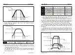
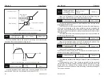
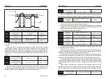
During the running of the inverter, when the set frequency is less than or
equal to the dormant frequency of P8-51, after the delay time of P8-52, the
inverter enters the sleep state and stops automatically.
In general, please set the wake-up frequency (P8-49) to be greater than
or equal to the dormant frequency (P8-51). When the wake-up frequency and
sleep frequency are both set to 0.00 Hz, the sleep and wake-up functions are
invalid.
This set of parameters is used to implement sleep and wake-up functions
in water supply applications.
When the dormant function is enabled, if the frequency source is PID,
whether PID operation is performed in the dormant state is determined by
FA-28. In this case, select PID operation enabled in the stop state (FA-28 =
1).
If the inverter is in the sleep state and the current running command is
valid, when the set frequency is greater than or equal to the P8-49 wake-up
frequency, after the delay time of the time P8-50, the inverter starts to start.
P8-53
Current running
time reached
0.0Min
〜
6500.0Min
Default
:
0.0
Chapter 6
Chapter 6


