User Manual
User Manual
77
76
A frame message must be transmitted in a consecutive data stream; if the
interval is more than 1.5-byte transmission time before transmission of the
whole frame is finished, those incomplete messages will be cleared by the
receiver which will take the next byte as part of address field of new frame by
mistake; likewise, if the interval is less than 3.5-byte transmission time, the
receiver will identify it as the extension of last frame. Because of disorder of
frames, CRC value will be incorrect, which may result in malfunction.
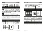
Standard Structure of RUT Frame :
Frame Format of RTU Data
MODBUS Message
Initiate:
a interval
of
3.5 bytes
at least
Function
code
Data Verification
Terminate:
a
interval of
at
least
3.5 bytes
Slave
address
9.4 Command code & data description
9.4.1 Format of No.1 address for Setting as follows, setting frequency 50Hz
(PO-03)
Superior host command:
Converter's response:
Frame header
T1-T2-T3-T4 (3.5-byte transmission time)
Slave address field
Communication address: 0~147(decimal system) /
(Zero stands for broadcast communication address)
Function domain
(CMD)
0x03: reading parameters of slave controller
0x06: programming parameters of slave controller
Data field
ENTER (N-1)
… ENTER
(
0)
2*N-byte data is not only the main content of
communication but also the core of data exchange
during the communication.
Checksum
Estimated value: CRC value (16BIT)
Frame ending
T1-T2-T3-T4 (3.5-byte transmission time)
Frame header
Address
Function code
Register address
Register information
Checksum
END
3.5-byte interval
0x01
0x06
0x0003
0x01F4
0x79DD
3.5-byte interval
Frame header
Address
Function code
Register address
Register information
Checksum
END
3.5-byte interval
0x01
0x06
0x0003
0x01F4
0x79DD
3.5-byte interval
9.4.2 Format of No.1 address for reading as follows, setting
frequency (PO-03)
Note: register number must be one only when reading
Superior host command:
Converter's response:
9.4.3 Frame format of response error as follows, setting frequency
60Hz (PO-03)
Type of error:
01H - Data address overrun
02H - Number of data overrun & read-in data content exceeding bounds
(ceiling & floor)
03H - Operating, no read-in data are permitted
9.4.4 CRC Mode
RTU frame format is mainly applied to CRC (Cyclical Redundancy
Check), error detecting field based on CRC is included in the message. CRC
domain can detect all the information of message, which is two bytes with
16-bit binary value included. It will be added into the message after the
calculation of transmission devices. The receiver will recalculate the CRC
receiving the message, and compare it with the values in the CRC domain
received by devices; if the CRC value is not equivalent to another one, it
proves that there is error in the transmission.
Frame header
Address
Function code
Register address
Register information
Checksum
END
3.5-byte interval
0x01
0x03
0x0003
0x0001
0x740A
3.5-byte interval
Frame header
Address
Function code
Register address
Register information
Checksum
END
3.5-byte interval
0x01
0x03
0x02
0x01F4
0xB853
3.5-byte interval
Frame header
Address
Function code
Register address
Register information
Checksum
END
3.5-byte interval
0x01
0x06
0x0003
0x0258
0x7950
3.5-byte interval
Superior host command:
Converter's response:
Frame header
Address
Function code
Error code
Checksum
END
3.5-byte interval
0x01
0x86
0x02
0xC3A1
3.5-byte interval
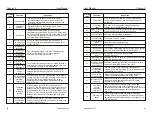
Note : Tuning supports motor tuning in keyboard operation mode, terminal
mode and communication mode.
3 : Applicable to the case of no encoder, self-learning of the motor
parameters under the static state of the motor (the motor may still have
slight jitter at this time, need to pay attention to safety)
Asynchronous machine static tuning (P1-00~P1-05 must be set
correctly) can get three parameters P1-06~P1-08.
2 : Complete auto-tuning to ensure the dynamic control performance of the
frequency converter, please select the full tuning.
Action Description: Set the function code to 2, then press the RUN button,
the inverter will perform a complete tuning.
Before the asynchronous machine is fully tuned, the motor must be
disconnected from the load to keep the motor in no-load state. The
parameters P1-00~P1-05 must be correctly set. (The encoder pulse
number P1-27 must be set under the closed-loop control with PG card.)
The inverter can obtain five motor parameters P1-06~P1-10, AB phase
sequence P1-30 (with PG card) of the encoder, and vector control current
loop PI parameters P2-13~P2-16.
Action description: Set the function code to 3, then press RUN key, the
inverter will perform no-load tuning.
Action Description: Set the function code to 1, then press the RUN button,
the inverter will perform static tuning.
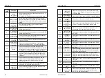
P2-00
Speed loop
proportional gain 1
1
〜
100
Default
:
30
Speed loop
integration time 1
0.01s
〜
10.00s
Default
:
0.50s
Switchover
frequency 1
0.00
〜
P2-05
Default
:
5.00Hz
Speed loop
proportional gain 2
1
〜
100
Default
:
20
Speed loop
integration time 2
0.01s
〜
10.00s
Default
:
1.00s
Switchover
frequency 2
P2-02
〜
Maximum frequency Default
:
10.00Hz
P2: Vector control parameter
P2 function code is valid only for vector control and invalid for VF control.
P2-01
P2-02
P2-03
P2-04
P2-05
The inverter runs at different frequencies and can select different speed
loop PI parameters. When the running frequency is less than the Switchover
frequency 1 (P2-02), the speed loop PI adjustment parameters are P2-00
and P2-01. When the running frequency is greater than the Switchover
frequency 2, the speed loop PI adjustment parameters are P2-03 and P3-04.
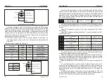
Switching the speed loop PI parameter between frequency 1 and frequency
2, linearly switching between two sets of PI parameters, as shown in Figure
6-2.
Figure 6-2 PI Parameter diagram
PI parameter
P2-00
P2-01
P2-03
P2-04
Frequency command
P2-02
P2-05
Note: If the PI parameters are not set properly, the speed overshoot may
be too large. An overvoltage fault occurs even when the overshoot falls back.
Increasing the proportional gain and reducing the integration time can
speed up the dynamic response of the speed loop. However, if the
proportional gain is too large or the integration time is too small, the system
can oscillate. The recommended adjustment method is:
If the factory parameters do not meet the requirements, fine-tune the
Default parameter, first increase the proportional gain to ensure that the
system does not oscillate; then reduce the integration time, so that the
system has faster response characteristics, overshoot and smaller.
The speed dynamic response characteristic of the vector control can be
adjusted by setting the proportionality factor and the integration time of the
speed regulator.
Chapter 6
Chapter 6


