


INSTALLATION
2-1 Installation environment
•
Locations free of water droplets, vapors, dust and oily dust.
•
Non-corrosive, flammable gas and liquid.
•
No floating dust metal particles.
•
The environment temperature is -10°C
~
50°C. If the environment
temperature exceeds 40°C, please place it in a well ventilated place
and delete the inverter
•
Strong and vibration-free place.
•
Locations without electromagnetic noise interference.
2-2 Installation method and space
•
The inverter should be installed on a structure that does not burn, such
as metal, otherwise a fire accident may occur.
•
The inverter should be installed vertically and securely with screws. Do
not flip, tilt or install horizontally. When the inverter runs, heat is
generated. To ensure the passage of the cooling air, a certain space is
left during installation (as shown in the figure).
•
When installing the inverter in the control cabinet, consider ventilation
and heat dissipation to ensure that the ambient temperature of the
inverter does not exceed the specified value. Do not install the inverter
in a closed box with poor ventilation.
•
When installing multiple inverters in the same control cabinet, it is
recommended to install them side by side in order to reduce the
thermal impact between each other. If it is necessary to install up and
down, a partition plate must be provided to reduce the influence of heat
generated in the lower part on the upper part (as shown in the figure).
•
Do not allow foreign matter such as various fibers, paper sheets, chips
(chips) or metal fragments to enter the inverter.
50mm
50mm
≥
100mm
≥
100mm
UP
Right
CONVERTER
CONVERTER
CONVERTER
User Manual
User Manual
Chapter 2
Chapter 3
7
6
Installation size
Power level
≤
15kw
18.5~30kw
≥
37kw
≥
50mm
≥
300mm
≥
50mm
≥
200mm
≥
20mm
≥
100mm
A
B
WIRING
In order to ensure the safety of operators and inverters, it is
necessary to be operated by qualified professional electricians. The
following are special considerations when wiring :
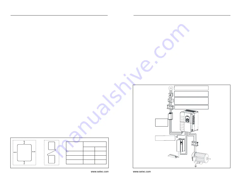
3-1 Peripheral device connection
•
Make sure the input power is off before wiring.
•
The ground terminal of the inverter must be reliably grounded.
•
Verify that the rated voltage of the inverter matches the AC power
supply voltage.
•
The power cable must be connected to the R, S, and T terminals of the
inverter. The motor cable should be connected to the U, V, and W
terminals. Do not connect the fault. Otherwise, the inverter will be
damaged internally.
•
Confirm that the terminals and wires are reliably connected, and the
screws of the main circuit terminals are secured.
•
Do not touch the main circuit terminals, otherwise there is danger of
electric shock.
Breaker
AC reactor
Electromagnetic
contactor
Noise Filter
Braking Unit
Noise Filter Name
Select the
appropriate
model, the
rated current
is not less than
1.5 times the
rated current
of the inverter
Used to
improve
input power
factor
Instruction
Configuration
Three-phase
power
Braking
unit
(+)
(-)
R
U
S
V
T
W
M
Used to
control power
on and off
Used to
reduce the
radio
interference
generated
by the
inverter
It is optional when
the braking torque
can’t meet the
requirements
of use. It is
suitable for large
inertia load and f
frequent start and
stop.
It is used to
reduce the
radio
interference
on the output
side of the
inverter.
MC
Braking unit
AC output reactor
Braking resistor
Motor
Use within the allowable power supply
specification of the AC drive
Select a proper breaker to resist large
in-rush current that flows into the AC drive
at power-on.
To guarantee safety, use an electromagnetic
contactor. Do not use it to start or stop
the AC drive because such operation reduces
the service life of the AC drive.
Suppress the high order harmonic to improve
the power factor.
Three-phase AC
power supply
Moulded case circuit
breaker (MCCB) or earth
leakage circuit breaker
(ELCB)
Electromagnetic
contactor
AC input
react or
Noise filter on
input side
Reduce the
electromagnetic
interference on
the input side
Reliably ground the motor and
the AC drive to prevent electric
shock.