


User Manual
User Manual
73
72
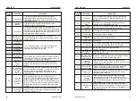
Motor
1. Vibration a
nd
temperature
rise
2. Noise
I/O
parameters
1. Input voltage
2. Output
current
8-2 Inspection and replacement of damageable parts
Fan must be replaced after more than 20,000 hours' running.
Electrolytic capacitor must be replaced after 30,000~40, 000 hours'
running
As for some of internal components, abrasion or performance
degradation may be caused during use. To ensure stable and reliable
operation, preventive maintenance on converter must be conducted. If
necessary, please replace them:
√
√
1. Stable operation and
normal temperature
2. No malfunction or
abnormal noise
1. Input voltage is within
specified range
2. Output current is lower
than rated value
8-3 Storage
This product can't be taken out from box until it's about to be installed. To
ensure that it's still valid for warranty and available for maintenance in the
future during the period of storage, please pay attention to the following
points:
0
•
Ambient temperature must be within the range between -20 C and
0
60
C
;
•
It must be protected from caustic gas or liquid;
•
Converter must be stored in a dry place where there is no dust;
•
Relative humidity must be within the range between 0% and 95%; no
condensation is permitted;
•
It must be packed properly and put on the shelf or desk.
Items
Examination period
non-peri
odical
regular
Check points
Criterion and
Maintenance
8-4 Product Warranty
Any of the following situations will be our company's responsibility,
which will be considered and guaranteed:
•
The warranty period for this product is 18months but only 12 months for
final buyer. During the period, any damage or fault without any wrong
operation will be our responsibility to fix, which is free of charge.
Maintenance fee will be charged accordingly if warranty expires.
•
Regarding the faults caused by the following points, extra fee will need to
be charged as service fee:
1. Fault caused by faulty operation which is not in conformity with manual
or specification
2. Fault caused by unauthorized maintenance modification;
3. Damage caused during the transportation or improper safekeeping;
4. Fault caused by misuse failure
5. As for the damages caused by fire, salt corrosion, gaseous corrosion,
earthquake, storm, flood, thunder strike, abnormal voltage and other
irresistible factor, despite of the expiration of warranty, any
compensable maintenance service will be provided by our company
for good.
P0-22
Frequency
reference resolution
1
:
0.1Hz
2
:
0.01Hz
Default
:
2
Note : When modifying the function parameters, the decimal places of all
frequency-related parameters will change and the corresponding frequency
values will also change.
When the frequency resolution is 0.01 Hz, the maximum output frequency is
600.00 Hz.
When the frequency resolution is 0.1Hz, the maximum output frequency can
reach 3200Hz.
This parameter is used to determine the resolution of all frequency-
dependent function codes.
P0-23
Digital setting
frequency shutdown
memory selection
0: Not retentive
1: Retentive
Default
:
0
keyboard ▲, ▼ key or terminal UP, DOWN remains valid.
0 : It means that after the inverter stops, the digital set frequency value will
return to the value of P0-08. The frequency modified by the keyboard ▲,
▼ key or terminal UP, DOWN will be cleared
1 : means that after the inverter stops, the digital set frequency retains the set
frequency of the last stop time, and the frequency modified by the
P0-24
Motor parameter
group selection
0: Motor parameter group 1
1: Motor parameter group 2
Default
:
0
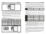
The inverter drives the application of 2 motors in time division. The 2
motors can set the motor nameplate parameters, independent parameter
tuning, select different control modes, and independently set parameters
related to running performance.
Motor parameter group 1 the corresponding function parameter group is
F1 group and F2 group, and motor parameter group 2 corresponds to function
parameter group A2 group. The user can select the current motor parameter
group via the F0-24 function code, or switch the motor parameters via the
digital input terminal X.
When the function code selection conflicts with the terminal selection, the
terminal selection is subject to.
P0-25
Acceleration/
Deceleration
time base frequency
0: Maximum frequency (P0-10)
1: Set frequency 2: 100Hz
Default
:
0
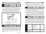
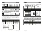
Acceleration/deceleration time refers to the acceleration/deceleration
time from zero frequency to the frequency set by P0-25. See Figure 6-1.
When P0-25 is selected as 1, the acceleration/deceleration time will
change with the change of the set frequency.
P0-26
Base frequency for
UP/DOWN
modification during
running
0: running frequency
1: setting frequency
Default
:
0
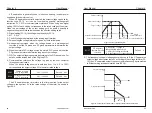
This parameter is valid only when the frequency source is digitally set.
When used to determine the ▲, ▼ key or terminal UP/DOWN action of
the keyboard, the target frequency is increased or decreased based on the
operating frequency, or is increased or decreased based on the set
frequency.
The difference between the two settings is obvious when the inverter is in
the acceleration/deceleration process, that is, if the running frequency of the
inverter is different from the set frequency, the different choices of the
parameters are very different.
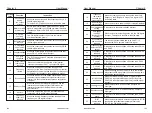
P0-27
Binding
command source
to frequency
source
Single digit : operation panel
command binding frequency source
selection
0: No binding
1: Digital setting frequency
2: AI1 3 : AI2 4: AI3
5: Pulse X6 6: Multi-speed
7: Simple PLC 8: PID
9: Communication given
Tens: terminal command binding
frequency source selection
Hundreds: Communication command
binding frequency source selection
Default
:
0000
Define the bundle combination between the three running command
channels and the nine frequency references to facilitate synchronous
switching.
The above frequency given channel has the same meaning as the main
frequency source X selects P0-03. Different running command channels can
bundle the same frequency given channel. When the command source has a
bundled frequency source, the frequency source set by P0-03~P0-07 is no
longer active during the valid period of the command source.
Chapter 6
Chapter 6


