


P3-02
User Manual
User Manual
81
80
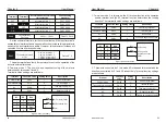
The parameter above is used to set transmission rate of the data between
superior controller and converter.
Note: the Baud rate of superior controller and converter should be the same;
therwise, communication cannot be conducted.
The data format of superior controller and converter should be the same;
otherwise, communication cannot be conducted.
9600
Factory default
Baud rate
No checking: 8-N-1
Data format
Factory default
The data format of superior controller and converter should be the same;
otherwise, communication cannot be conducted.
1
P0-15
Factory default
Factory default
Setting range
1-127 (Zero stands for broadcast address)
For other relevant functional parameters, Please refer to P5-25 ~ P5-29
instructions.
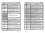
9.6 Parameter description of communication
Fault address
Data Description
Register
address
Address
S/N
0xF1
242
1: Storage fault
3: Undervoltage
4: Overvoltage
5: Overload
6: Overcurrent
7: Input default phase
8: Output default phase
9: Output short circuit
10: System fault
11: External fault
12: PI fault
13: Overtemperature
14: Overcurrent
15: Motor Overload
16: Contactor OFF
20: Signal failure of current
detection
21: Communication Fault
Function
Code
Description
Description and Range
Default
P0-01
Frequency
setting
mode
0 : Frequency setting (UP/DOWN)
1 : Panel potentiometer
2 : External AI1
3 : External AI2
4 : PI regulation
5 : UP/DOWN by the P5-20
add and subtract
6 : UP/DOWN by the P5-20 add and
subtract, frequency qing zero downtime
7: Frequency communication reference
0
P0-02
Control mode
for
running
0
0 : Controlled by keyboard
1 : Controlled by terminals,
STOP Key disabled
2 : Controlled by terminals,
STOP Key enabled
3 : Controlled by communication
For a given frequency of communication, you can set P0-01 =7 and the
corresponding address is 1003 (decimal). If it is given in other ways,
please set it as required.
Start and stop the frequency converter through communication,
the corresponding address is 200 (decimal)
P0-15
Modbus address
1
1~247
The uniqueness of the local address is the basis for the point-to-point
communication between the host computer and the converter
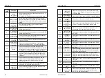
P5-25
Communication
baud rate
5
2 : 1200BPS
3 : 2400BPS
4 : 4800BPS
5 : 9600BPS
6 : 19200BPS
7 : 38400BPS
This parameter is used to set the data transmission rate between the upper
computer and the frequency converter. Note that the baud rate set by the upper
computer and the frequency converter must be consistent, otherwise the
communication cannot be carried out.
P5-26
Modbus data
format
0
1 : No check (8-n-2)
0 : No check (8-n-1)
3 : odd parity (8-o-1)
2 : Even parity (8-e-1)
the data format set by upper computer and frequency converter must be consistent,
otherwise, communication cannot be carried out.
P5-27
Modbus response
delay
20
0 ~ 200ms
Refers to the interval time between the end of data receiving of the inverter and data
sending to the uploaded. If the response delay is less than the system processing
time, the response delay shall be subject to the system processing time. If the
response delay is longer than the system processing time, the system shall delay
and wait after processing the data until the response delay time is reached before
sending the data up to the computer
P5-28
Serial
communication
timeout
0.0
0.1
~
60.0s
0.0: invalid (not detected)
P5-29
Communication
abnormal action
selection
0
0 : continue running
1 : alarm and shutdown
When the function code is set to P5-28 = 0.0s, the communication timeout
parameter is invalid. When the P5-28 function code is set to a valid value, if the
interval between one communication and the next communication exceeds the
communication timeout, and P5-29 = 1, the system will report a communication
failure error (CE) and stop. Typically, it is set to invalid. If you set this parameter on
a continuously communicating system, you can monitor the state of communication
This parameter only takes effect when the motor is running above the
rated frequency. When the motor needs to accelerate to 2 times the rated
motor frequency and the actual acceleration time is longer, reduce P2-21
appropriately; when the motor runs at 2 times the rated frequency and the
speed drops greatly, increase P2-21 appropriately. Generally no need to
change.
V/F Curve
setting
0: Straight line V/F
1: Multi-point V/F
2: square V/F
3: 1.2 power V/F
4: 1.4 power V/F
6: 1.6 power V/F
8: 1.8 power V/F
9: reserved
10: V/F complete separation mode
11: V/F semi-separation mode
Default
:
0
P3-00
P3: V/F control parameter
This group of function codes is valid only for V/F control and invalid for vector
control. V/F control is suitable for general-purpose loads such as fans and
pumps, or an inverter with multiple motors, or applications with large
differences in inverter power and motor power.
Assuming that the voltage source input is X (X is 0~100%), the
relationship between the inverter output voltage V and the frequency F is:
V/F=2 * X * (motor rated voltage) / (motor rated frequency)
0 : Straight line V/F. Suitable for ordinary constant torque loads.
1 : Multi-point V/F. Suitable for loads such as dehydrators and centrifuges.
Set the P3-03~P3-08 parameters to get any V/F curve.
3~8: V/F relationship between straight line V/F and square V/F.
11 : V/F semi-separation mode. In this mode, V is proportional to F, but the
proportional relationship can be set by P3-13, and the relationship
between V and F is also related to the rated voltage and rated frequency
of the motor of P1 group.
2 : square V/F. Suitable for centrifugal loads such as fans and pumps.
10 : V/F complete separation mode. At this time, the output frequency of the
inverter is independent of the output voltage, the output frequency is
determined by the frequency source, and the output voltage is
determined by P3-13. Generally used in induction heating, inverter
power, torque motors and other occasions.
Torque boost
0.0%
(
Auto
)
0.1%
〜
30.0%
depend
Cut-off frequency
of torque boost
0.00Hz
〜
Maximum frequency Default
:
50.00Hz
P3-01
In order to compensate for the low-frequency torque characteristics of the
V/F control, some boost compensation is applied to the output voltage of the
inverter at low frequencies. However, the torque boost setting is too large, the
motor is prone to overheating, and the inverter is prone to overcurrent.
It is recommended to increase this parameter when the load is heavy and
the motor starting torque is insufficient. The torque boost can be reduced
when the load is light.
When the torque boost is set to 0.0, the inverter is automatically torque
boosted. At this time, the inverter automatically calculates the required
torque boost value according to parameters such as the stator resistance of
the motor.
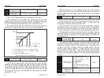
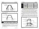
Torque boost cutoff frequency: Under this frequency, the torque boost is
valid. If the set frequency is exceeded, the torque boost will be invalid, as
shown in Figure 6-3.
f1
fb
Output voltage
Vb
Output frequency
V1 : Manual torque boost voltage
Vb :manual torque boost cutoff frequency
Vb : Maximum output voltage
fb : Rated operating frequency
V1
Figure 6-3 Manual torque boost
Multi-point V/F
frequency point 1
0.00Hz
〜
P3-05
Default
:
0.00Hz
Multi-point V/F
voltage point 1
0.0%
〜
100.0%
Default
:
0.0%
Multi-point V/F
frequency point 2
P3-03
〜
P3-07
Default
:
0.00Hz
Multi-point V/F
voltage point 2
0.0%
〜
100.0%
Default
:
0.0%
P3-03
P3-04
P3-05
P3-06
Chapter 6
Chapter 6