


User Manual
User Manual
71
70
•
Air switch of power source trips when power on
Please check whether rectifier bridge is burned; if it's damaged, please
seek for technical support.
Please check whether power source is grounded or short-circuited;
please solve it accordingly.
•
Motor doesn't start running after converter is started
Please check whether there is three-phase symmetrical output among U,
V, W. If there is, motor or its circuit is damaged mostly; or stalling may be
caused by mechanical problem. please solve it accordingly.
If there is output voltage, then driver board or output module may also be
damaged.
If three-phase output is unsymmetrical, then driver board or output
module of converter may be damaged. Please seek for technical support.
Please also seek for technical support.
•
Air switch of power source trips while running
Please check whether output modules between phase and phase are
short-circuited; if there is short circuit, please seek for technical support.
Please check whether motor lines are short-circuited or grounded; if they
are, please solve it accordingly.
If stripping take places sometimes, not regularly; and there is a long
distance between motor and converter, please take the installation of
additional AC reactor into consideration.
Only the qualified engineer is allowed to conduct maintenance for
converter; please pay attention to the following precautions:
•
Do not touch the components on the PCB directly; otherwise,
components can be damaged by static easily.
•
Maintenance must be conducted by qualified engineer in specified way;
•
Only when converter is shut down for 5 minutes can maintenance be
conducted;
•
Make sure that all the screws are fastened after the maintenance.
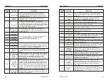
8-1 Daily Maintenance and Upkeep
Affected by environmental conditions(e.g. temperature, humidity or
smog) and aging of internal components, converter may malfunction.
Therefore, daily inspection and maintenance on converter must conducted
during the process of storage and application. For the detailed information of
daily inspection and maintenance, please refer to the following table:
Items
Examination period
non-peri
odical
regular
Check points
Criterion and
Maintenance
Environ-
mental
conditions
1. Temperature
humidity
2. Dust & mist
3. Gas &
0
1. Temperature <40 C,
humidity < 90%, no frost
2. No odor, No flammable
or explosive gas
Cooling
system
1. Installation
environment
2. Built-in fan
1. Good ventilation, no
obstruction of ventilation
duct
2. Normal operation of built-
in fan, no abnormal noise
MAINTENANCE
Converter
1. Vibration
temperature
rise
2. Noise
3. Dust or
impurity
4. lead and
terminals
1. Stable v
ibration, n
ormal
blast temperature
2. No abnormal noise or
odor
3. Remove dust by dry
compressed air
4. No loose screws
√
√
√
When the upper limit frequency is analog or pulse setting, P0-13 is used
as the offset of the set value, and the offset frequency is superimposed with
the upper limit frequency value set by P0-11 as the set value of the final upper
limit frequency.
P0-14
Frequency lower
limit
0.00Hz
〜
frequency upper
limit P0-12
Default
:
0.00Hz
When the running frequency is lower than the lower limit frequency, the
inverter can choose to stop, run at the lower limit frequency or run at zero
speed, set by P8-14.
P0-15
Carrier frequency
0.5kHz
〜
16.0kHz
Model
dependent
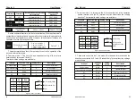
Adjusting the carrier frequency will affect the following performance :
This function is used to adjust the carrier frequency to reduce motor noise,
avoid mechanical resonance points, and reduce ground leakage current and
interference. When the carrier frequency is low, the output current higher
harmonic component increases, the motor loss increases, and the motor
temperature rise increases. When the carrier frequency is high, the motor
loss is reduced, the motor temperature rise is reduced, but the temperature
rise of the inverter is increased, and the interference is increased.
Carrier
frequency
Motor
noise
Output
current
wave
Motor
temperature
rise
Inverter
temperature
rise
Leakage
current
External
radiation
interfere
Low
Big
Bad
High
Low
Small
Small
High
Small
Good
Low
High
Big
Big
The frequency setting of the carrier frequency is different for inverters with
different powers. If the carrier frequency is set higher than Default, the
temperature rise of the inverter radiator will increase. At this time, the user
needs to derate the inverter, otherwise the inverter has the danger of
overheating alarm.
P0-16
Carrier frequency
is adjusted with
temperature
0 : no
1 : yes
Default
:
1
When the inverter detects that its own temperature is high, it automatically
reduces the carrier frequency to reduce the temperature rise of the inverter.
When the temperature is low, the carrier frequency is gradually restored to the
set value. This function can reduce the chance of the inverter overheating
alarm.
depending
P0-17
0.00s
〜
65000s
Acceleration time 0
Deceleration time 0
0.00s
〜
65000s
depending
P0-18
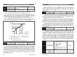
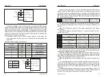
Acceleration time refers to the time required for the inverter to accelerate
from zero frequency to the acceleration/deceleration reference frequency
(P0-25), see t1 in Figure 6-1.
Deceleration time refers to the time required for the inverter to decelerate
to the zero frequency from the acceleration/deceleration reference
frequency (P0-25), see t2 in Figure 6-1.
The inverter provides 4 sets of acceleration/deceleration time (P8-03~P8-
08), and the user can switch from the input terminal.
Figure 6-1 Acceleration and deceleration time
Ourput frequency
Setting frequency
Set acceleration time
Acceleration deceleration
reference frequency
Actual acceleration time
Actual
deceleration time
Set deceleration
time
Time
Acceleration/
deceleration unit
0
:
1s 1
:
0.1s 2
:
0.01s
Default
:
1
P0-19
Used to set 3 acceleration and deceleration time units, which are 1
second, 0.1 second and 0.01 second respectively.
Note : After modifying this parameter, the decimal places displayed in
each acceleration/deceleration time will change, and the corresponding
acceleration/deceleration time will also change.
Auxiliary frequency
source offset
frequency when
superimposing
0.00Hz
〜
Maximum frequency
P0-10
Default
:
0.00Hz
P0-21
When the frequency source is used as the main auxiliary operation, P0-
21 is used as the offset frequency, and the result of the main and auxiliary
operations is superimposed as the final frequency setting value, so that the
frequency setting can be more flexible.
t1
t2
Chapter 6
Chapter 6