background image

-20-

Connecting to a computer   

B

USB

B

USB

1.

Operating mode

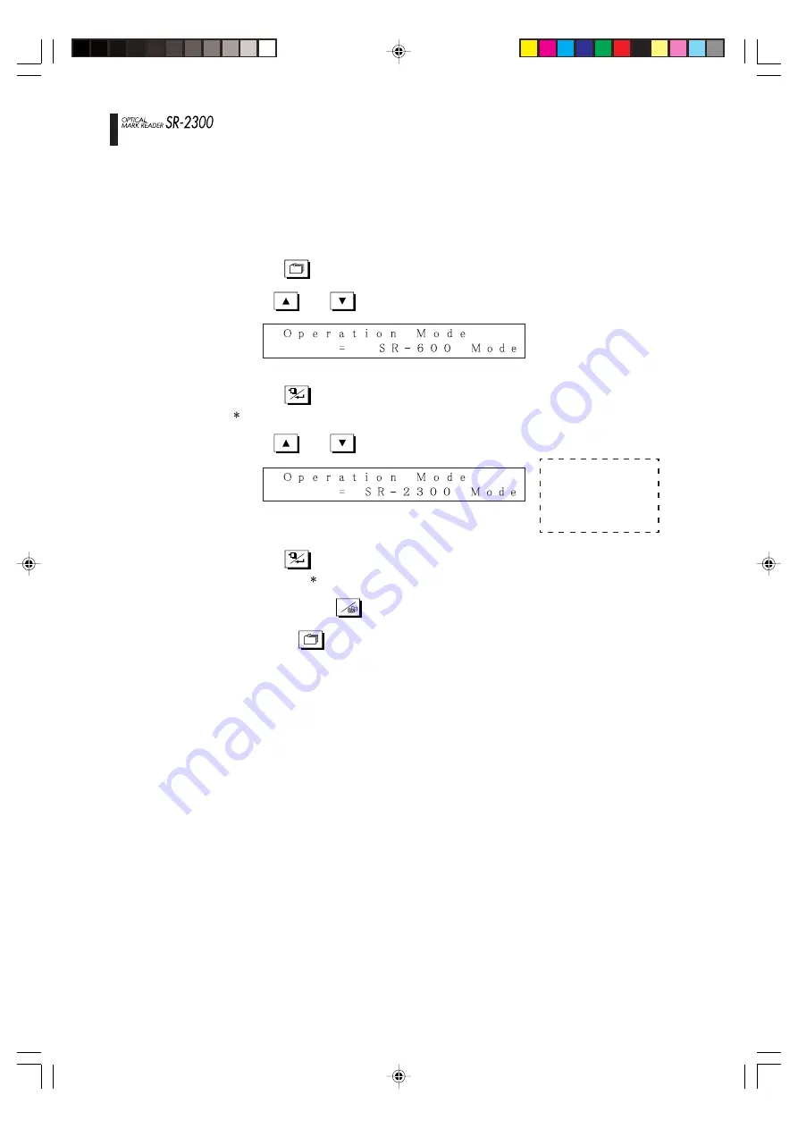
Select the SR-2300 mode as the operating mode.

(1)

Press the 

MENU

 switch to enter the menu mode.

(2)

Use the 

UP

 and 

DOWN

 switches to select the mode shown below.

Press the 

FEED/ENTER

 switch to start [Operation Mode] setting.

(“ ” mark flashes in the first column of the first line on the LCD.)

(3)

Use the 

UP

 and 

DOWN

 switches to select the SR-2300 mode.

Press the 

FEED/ENTER

 switch to save the selected mode into memory.

(The flashing “ ” mark disappears from the LCD.)

(4)

Keep pressing the 

C

CLEAR/EXIT

 switch until it returns to normal mode,

or press the 

MENU

 switch to return to normal mode.

Operation mode
setting values
• SR-600 mode
• SR-2300 mode

Summary of Contents for SR-2300

Page 1: ...equency energy and if not installed and used in accordance with the instructions may cause harmful interference to radio communications However there is no guarantee that interference will not occur i...

Page 2: ...ng power on 15 BLoading paper 16 BSetting paper weight 17 Marking instructions 18 Connecting to a computer 19 BUSB 1 Operating mode 20 2 Interface settings 21 BRS 232C 1 Operating mode 22 2 Interface...

Page 3: ...ying various information BDisplaying the version 41 BDisplaying front surface reading sensor data 42 BDisplaying back surface reading sensor data 43 BDisplay options 44 Operating tests BFeed test 1 45...

Page 4: ...to the main text of this manual Warning Improper operation by neglecting these instructions may result in death or serious injury Caution Improper operation by neglecting these instructions may resul...

Page 5: ...at could cause fire or electric shock J Do not remove the cover from this device That could cause electric shock Ask the sales shop to conduct any internal checking adjustment or repair J Do not modif...

Page 6: ...injury J If you must touch the paper feeding surface of the main body be careful not to allow your fingers to be caught or hit J When maintaining the device for your safety be sure to remove the power...

Page 7: ...use it as an example when designing entry sheets Check sheet use it for checking OMR operations 5 Operating manual this booklet 6 A4 check sheets 5 sheets A4 mark entry sheets 5 sheets 8 USB cable Op...

Page 8: ...general rule the company will keep the product temporarily to carry out such repair work Malfunctions and other failures caused by customer misuse will not be covered by the warranty For details plea...

Page 9: ...the power switch is on 2 Do not move the device while it is operating Also do not touch pull or push paper 3 Do not put objects on the device or sit or lean on it 4 Do not give the device a strong sh...

Page 10: ...10 Names of parts Names of parts Side guide Paper feeding table hopper Display panel LCD Operating buttons Lock lever Power switch Guide lever lock Power connector Paper weight setting dial Interface...

Page 11: ...mal mode Drops the paper feeding table 2 Menu mode Use it to choose menu items and to select parameters If you press and hold the switch for one second menu items and parameters automatically scroll d...

Page 12: ...al and lowercase letters Numbers 0 9 36 symbols half width katakana PC interface USB Ver 1 1 12Mbps RS 232C 9 600 115 200bps Display panel and Display panel LCD 20 characters x 2 lines operating switc...

Page 13: ...the protecting tapes after placing the device in an appropriate location Operation BPreparation 2 Install auxiliary brackets on the paper receiver 3 Install the paper receiver on the main device Hook...

Page 14: ...14 4 Connect the power cord to the main device 5 Connect the power cord to the power outlet Operation BPreparation...

Page 15: ...s initialized 3 The motor and other components are activated to check startup conditions 4 Check if the following message appears on the display panel LCD 5 Error messages may appear between steps 2 a...

Page 16: ...o the side guide index A maximum of 500 sheets of 105g m2 weight paper Note that overloading may result in paper not feeding or in reading errors Notes 1 Carefully handle paper so that it is not bent...

Page 17: ...per Weight of reading setting 2 1 Setting paper weight dial initially set to a paper weight of 105g m2 Align the arrow to the paper weight 2 Setting reading initially set to a paper weight of 105g m2...

Page 18: ...6 or darker Readable mark darkness can be adjusted You can check mark darkness using a diagnostic utility included in the package so check the darkness of the marks you want to read and adjust the re...

Page 19: ...speed on this device and the computer Set the computer data transfer speed by checking your computer or software manuals See the following pages to set the transfer speed for this device USB Operating...

Page 20: ...to start Operation Mode setting mark flashes in the first column of the first line on the LCD 3 Use the UP and DOWN switches to select the SR 2300 mode Press the FEED ENTER switch to save the selecte...

Page 21: ...llowing parameters Device ID setting value 0 126 and press the FEED ENTER switch to begin Device ID setting mark flashes in the first column of the first line on the LCD Set any number using the UP an...

Page 22: ...ng mark flashes in the first column of the first line on the LCD 3 Use the UP and DOWN switches to select the SR 600 mode Press the FEED ENTER switch to save the selected mode into memory The flashing...

Page 23: ...e value 5 Press the FEED ENTER switch to save the setting value into memory The flashing mark disappears from the LCD 6 Keep pressing the C CLEAR EXIT switch until it returns to normal mode or press t...

Page 24: ...ormal mode Character bit length value 7 8 2 3 Setting parity 1 Press the MENU switch to enter the menu mode 2 Use the UP and DOWN switches to select the following parameters and press the FEED ENTER s...

Page 25: ...he value 5 Press the FEED ENTER switch to save the setting value into memory The flashing mark disappears from the LCD 6 Keep pressing the C CLEAR EXIT switch until it returns to normal mode or press...

Page 26: ...e MENU switch to return to normal mode Flow control setting values RS CS Xon Xoff 3 Use the UP and DOWN switches to select Character Code setting and press the FEED ENTER switch mark flashes in the fi...

Page 27: ...0 columns 40 columns 0 2 inch S 1 40 columns 40 columns 0 25 inch 1 33 columns 33 columns 0 3 inch 1 27 columns 27 columns 0 3 inch F 1 24 columns 24 columns 3 Use the UP and DOWN switches to select S...

Page 28: ...switch to enter the menu mode 2 Use the UP and DOWN switches to select the following parameters and press the FEED ENTER switch 3 Use the UP and DOWN switches to select Reading Method setting and pres...

Page 29: ...nification setting and press the FEED ENTER switch mark flashes in the first column of the first line on the LCD 4 Use the UP and DOWN switches to set the value Magnification setting values Top end ti...

Page 30: ...witches to select the following parameters and press the FEED ENTER switch 3 Use the UP and DOWN switches to select Min Density Level setting and press the FEED ENTER switch mark flashes in the first...

Page 31: ...ches to select the following parameters and press the FEED ENTER switch Data reading settings BSetting density balance 3 Use the UP and DOWN switches to select Density Balance setting and press the FE...

Page 32: ...he UP and DOWN switches to select the following parameters and press the FEED ENTER switch 3 Use the UP and DOWN switches to select Reading Side setting and press the FEED ENTER switch mark flashes in...

Page 33: ...Mode setting and press the FEED ENTER switch mark flashes in the first column of the first line on the LCD 4 Use the UP and DOWN switches to set the value 5 Press the FEED ENTER switch to save the se...

Page 34: ...first column of the first line on the LCD 4 Use the UP and DOWN switches to set the value 5 Press the FEED ENTER switch to save the setting value into memory The flashing mark disappears from the LCD...

Page 35: ...enu mode 2 Use the UP and DOWN switches to select the following parameters and press the FEED ENTER switch 3 Use the UP and DOWN switches to select Paper Weight setting and press the FEED ENTER switch...

Page 36: ...g error detection Yes or No Yes Double feeding detection Yes or No Yes Left end skew detection Yes or No Yes Mark skew detection Yes or No No If mark skew detection is on number of rows 1 155 rows 1 r...

Page 37: ...evious table for setting values 5 Press the FEED ENTER switch to save individual setting values into memory The flashing mark disappears from the LCD 6 Keep pressing the C CLEAR EXIT switch until it r...

Page 38: ...press the FEED ENTER switch 3 Use the UP and DOWN switches to select Buzzer Control setting and press the FEED ENTER switch mark flashes in the first column of the first line on the LCD 4 Use the UP a...

Page 39: ...ress the FEED ENTER switch mark flashes in the first column of the first line on the LCD 4 Use the UP and DOWN switches to set the value 5 Press the FEED ENTER switch to save the setting value into me...

Page 40: ...ect Buzzer SoundQuality Adjustment setting and press the FEED ENTER switch mark flashes in the first column of the first line on the LCD 4 Use the UP and DOWN switches to set the value 5 Press the FEE...

Page 41: ...rmat 1 Press the MENU switch to enter the menu mode 2 Use the UP and DOWN switches to select the following parameters and press the FEED ENTER switch Displaying various information BDisplaying the ver...

Page 42: ...lect the following parameters and press the FEED ENTER switch 3 Use the UP and DOWN switches to select Type of Front Reading Sensor display and press the FEED ENTER switch 4 Use the UP and DOWN switch...

Page 43: ...ress the FEED ENTER switch 3 Use the UP and DOWN switches to select Type of Back Reading Sensor display and press the FEED ENTER switch 4 Use the UP and DOWN switches to display the settings Sensor pi...

Page 44: ...se the UP and DOWN switches to select Type of Option display and press the FEED ENTER switch 4 Use the UP and DOWN switches to display the options Reading sensor unit Reading sensor unit display data...

Page 45: ...arameters and press the FEED ENTER switch 3 Use the UP and DOWN switches to select Feed Test 1 4 Press the FEED ENTER switch to confirm the selection and display Feed Test 1 mark flashes in the first...

Page 46: ...FEED ENTER switch 3 Use the UP and DOWN switches to select Feed Test 2 4 Press the FEED ENTER switch to confirm the selection and display Feed Test 2 mark flashes in the first column of the first line...

Page 47: ...lashes in the first column of the first line on the LCD 5 Press the FEED ENTER switch to start the paper weight test The flashing mark disappears from the LCD and the test will start During operation...

Page 48: ...the rollers are stained the stains may rub off on cards or other various malfunctions may occur 2 Cleaning reading lens Clean the reader lens by softly wiping it with a clean cloth slightly wetted wi...

Page 49: ...d from the outlet 2 Grasp the lock lever to release the lock and push the top cover up to open it 3 Clean necessary parts 4 Close the top cover Slowly close the top cover and press it until there is a...

Page 50: ...er 1 100 000 or 3 years Double feeding Replace at the same time prevention roller 1 100 000 or 3 years as double feeding top prevention roller bottom Double feeding Replace at the same time prevention...

Page 51: ...51 External diagram Front view 575 371 7 292 6 212 Top view 365 255 56 3 Rear view Left view Right view Unit mm External diagram...

Page 52: ...only with mark skew detection 1 155 Rows O O Mark Skew Detection Level displayed only with mark skew detection 1 3 16 O X Buzzer Control Valid Invalid O O Buzzer Sound Adjustment displayed only when i...

Page 53: ...e None None None None Line error occurred between the device and the front surface reading unit Line error occurred between the device and the back surface reading unit Front surface reading unit does...

Page 54: ...AR switch or execute the clear error command 3 Cover open error Error Explanation Solution Cover open The cover of the main body is open Check if the cover of the main body is closed 4 Jam errors Erro...

Page 55: ...ng Error Explanation Solution Hopper empty Double feed error Left end skew error Mark skew error There is no paper in the hopper Two or more sheets were fed simultaneously Paper was fed crooked Mark l...

Page 56: ...clear error command Press the CLEAR switch or execute the clear error command Press the CLEAR switch or execute the clear error command Press the CLEAR switch or execute the clear error command Press...

Page 57: ...detected while the device is running The media detection element sensor detects paper jams Operational jams include double feeding jams and no feeding jams Skew Refers to paper that is slanted against...

Page 58: ...ng mark from the end of the timing mark Sensor for reading Reading sensor position sensor Sensors are photoelectrical elements that transform reflected light We use photo interrupters as reading senso...

Page 59: ...the Japan Chain StoresAssociation Bluish colored lines drop out when they are scanned with copy machines and other devices even if they don t use dropout color ink OCR paper for fax machines uses cold...

Page 60: ...aper feeding error and notifies user of the error PCS printed contrast signal Refers to the reflectance ratio contrast of printed marks symbols and letters as opposed to reflectance of non printed are...

Page 61: ...lace to put sheets to be processed for marking and compilation Start timing Stop timing Timing mark Mark frame Reading zone Light source Color tone Readable mark colors Unreadable mark colors waveleng...

Page 62: ...k to mark type with top end margin reading The reading zones are the front margin of the form as the first row and between timing marks as the second and subsequent rows 2 5mm Double feeding Refers to...

Page 63: ...r lower Print timing marks in ink at PCS 0 85 or higher 5 Printing position accuracy Parallelism Adjust printing parallelism for timing marks and data marks 0 2mm or less based on the cutting edge of...

Page 64: ...ion zones However do not print at PCS exceeding 0 15 in clear zones on the front surface in case of bleeding through from the back 10 ID mark Set an ID mark for identification as necessary Size 1 0mm...

Page 65: ...rizontal length W Pitch P x row 1 Do not aggregate tolerances P d b a 4 23 minimum Timing mark 9 or more c 1 5 or more 9 or more 4 23 minimum General tolerance 0 2 Unit mm A 1 6 6 99 3 81 1 27 11 43 0...

Page 66: ...s for 0 25 IBM card size Standard size 187 32 0 2 A 0 2 A 0 2 A 82 55 0 8 9 or more Minimum 1 5 or more 3 5 0 1 Standard size General tolerance 0 2 Unit mm A 6 35 x 11 69 85 Minimum 1 21 3 5 4 3 6 35...

Page 67: ...d b a 4 23 minimum Timing mark 9 or more c Example when 3 times is specified C x 1 5 9 or more 4 23 minimum General tolerance 0 2 Unit mm A 1 6 6 99 3 81 0 89 11 43 0 2 1 91 3 81 0 89 11 75 Size IBM P...

Page 68: ...rst row Reading zone of last row 1 6 6 99 3 81 1 5 11 43 0 2 1 91 3 81 1 5 11 75 Size IBM Postcard A5 B5 A4 8 5 9 Maximum number of columns a b c d 0 25 1 78 3 56 1 5 6 35 0 3 2 5 5 00 1 5 14 50 W x L...

Page 69: ...A 0 2 A 0 2 A 82 55 0 8 9 or more Minimum 1 9 or more 3 5 0 1 Standard size General tolerance 0 2 Unit mm 6 35 x 11 69 85 Minimum 1 5 3 5 4 3 6 35 6 35 Should be in the center between timing marks Re...

Page 70: ......

Reviews: