21
User Manual
Electrical Overview
Electrical Overview
This section describes the RMP components and how they interact.
System Components
A brief overview of each component is provided to help you become familiar with these components and their functions.
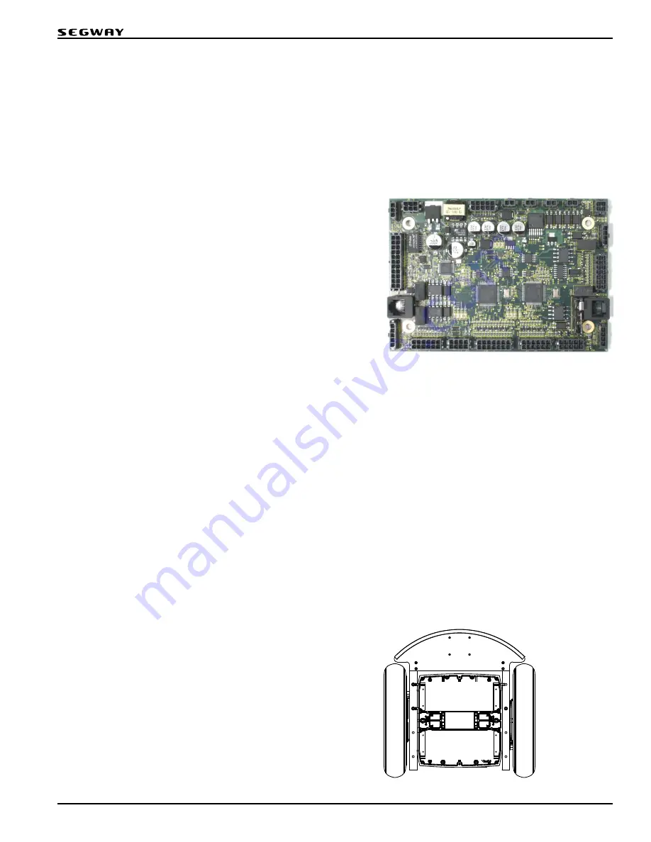
Centralized Control Unit
The Centralized Control Unit (CCU) contains the Segway Processor
(SP) and the User Interface Processor (UIP). These processors use
synchronized timing to control the RMP in real time. They communicate
via a Serial Peripheral Interface (SPI) link.
Powerbase
The powerbase is one of the main components of the Segway PT and has been leveraged for use as the propulsion unit of the RMP.
Each RMP 210 has one powerbase that controls both wheels. Inside the powerbase is one Motor Control Units (MCU 0) and an option
Balance Sensor Assembly (BSA). The powerbase is not serviceable by the user; this information is provided for completeness only.
Figure 15: Centralized Control Unit
Motor Control Unit
The MCU is a Segway motor drive. It utilizes the robustness of
the Segway PT propulsion system as a motor drive. Each MCU
has two motor drives that drive half of a dual hemisphere Segway
motor. Each MCU performs its own internal fault detection and
communicates with the SP via CAN interface. The user does not have
access to the MCU interface.
Balance Sensor Assembly
The BSA provides redundant raw three-axis inertial data to the SP.
The SP uses this information to compute the Pitch State Estimate
(PSE). The PSE algorithm estimates the machine orientation and
movement based on the combined raw inertial information and
wheel odometry.
Segway Processor
The SP controls essential system functions including timing
management, control algorithms, safety kernel functions,
redundancy management, estimation algorithms, and Segway
hardware interfaces. In addition, a real time clock and Non-Volatile
Memory (NVM) allow for diagnostic fault logging.
User Interface Processor
The UIP controls the interaction between the user and the RMP. It allows the user to command RMP motion, configure machine
parameters, and access faultlog information.
The UIP consists of four layers: System layer, I/O layer, Toolkit layer, and Application layer.
1. The System layer manages hardware-specific functionality like interrupts and timing.
2. The I/O layer manages all processor I/O including GPIO, ADC, DAC, CCP, USB, UDP, CAN, RS232, TTL Serial, and the SPI
link. The I/O layer is responsible for gathering all raw UIP data and presenting it to the Toolkit layer.
3. The Toolkit layer abstracts the information gathered by the I/O layer and interprets it into meaningful system level data.
The Toolkit layer then relays that information to various interfaces for consumption by the user.
4. The Application layer consists of an application stump for future expansion and development of the system.
Figure 16: Segway Powerbase
MCU 1
BSA
Rear
Summary of Contents for RMP 210 V3
Page 1: ...User Manual Segway Robotics Mobility Platform RMP 210 V3 Robotics...
Page 2: ......
Page 20: ...20 RMP 210 RMP 210...
Page 30: ...30 Powering On Off RMP 210...
Page 34: ...34 Connecting RMP 210...
Page 40: ...40 Maintenance RMP 210...
Page 49: ...49 User Manual Troubleshooting...
Page 50: ...Robotics 24927 00001 aa...


