background image

SL-C510-AIS

Compact 5-9NM Solar Marine Lantern

Latest products and information available at 

www.sealite.com

19

Custom – 

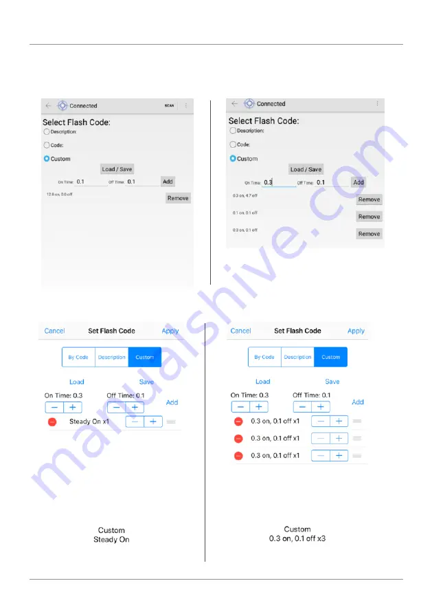
Create sequences of custom Flash Codes by nominating the on/off times. Once the 

Flash Code is established press “Set /Apply” to confirm the change. To add multiple flashing 

configurations, press “add” for each configuration. 

Summary of Contents for SL-C510-AIS

Page 1: ...SL C510 With AIS Compact 5 9NM Solar Marine Lantern V1 4 INSTALLATION SERVICE MANUAL ...

Page 2: ...J Ohle M Nicholson M Nicholson 1 1 Update AIS Battery images August 2019 M Dutka M Nicholson 1 2 Lantern Data Update July 2020 M Dutka M Nicholson 1 3 Update to AIS programming procedure November 2020 M Dutka M Nicholson 1 4 Grounding advice February 2021 M Dutka M Nicholsond ...

Page 3: ...ge 10 Accessing the SealitePro App for the first time Page 11 SealitePro Password Reset Procedure Page 13 Lantern Status Page 14 Solar Calculations Page 15 Programming Options Page 17 Manufacturing Data Page 23 SealitePro Troubleshooting Page 26 Optional IR Remote Control Page 28 GPS Synchronisation Page 35 Lantern Status Page 36 Lantern Thermal Management Page 37 Lantern Data Page 37 Thermal Limi...

Page 4: ...et Flash Code Technology Sealite is the world s fastest growing manufacturer of marine aids to navigation We employ leading mechanical optical hardware software engineers to create innovative products to service the needs of our customers worldwide and offer the widest range of solar powered LED lanterns in the marketplace Electronics Sealite employs leading in house electronic engineers in the de...

Page 5: ...s specifically designed for use with LEDs and incorporates an environment friendly spike to deter unwelcome bird life The lens design also ensures that vessel operators clearly see the light from above when passing the AtoN The design incorporates a conveniently located OLED Organic Light Emitting Diode screen with touchpad allowing maintenance personnel to check the diagnostics of the lantern wit...

Page 6: ...harged Alternatively the external charge port can be used to charge the battery charger sold separately Ensure battery voltage is 13V before placing into service Preferred Installation Location For best lantern performance ensure solar modules are not covered or in the shade and are in clear view of the sky will result in optimum charging results A clear GPS signal strength is required For locatio...

Page 7: ... the chassis ensuring the O ring is properly placed 4 Replace the four 4 socket head screws Sealite recommends that the light head be tightened onto the solar chassis base using a general purpose grip tool similar in shape to a screwdriver however with the appropriate hex key head fitted To achieve a satisfactory seal it is recommended that a torque of 3Nm is applied to the bolts used for holding ...

Page 8: ...gs status in a sequential manner unless the Touch Pad is activated for a second time this action will allow the OLED display to stop on the information showing at the Touch Action To visualise the remaining information simply Tap the Pad again then the system will display the next set of information When the Touch Pad device is inactive for more than three minutes the OLED display will enter in sl...

Page 9: ...ash Codes included in the appendix Displays the lantern operating intensity in percentage The SL C510 can provide four different intensity levels in percentage or with a step size of 3 125 or 1 32 nautical miles when set by range Low 25 Medium 50 Medium High 75 High 100 Indicates the lantern real time battery voltage level Displays the lantern current operating status This include the information ...

Page 10: ...ptions have been provided Programming the Lantern Bluetooth Controller Functions The Sealite SL C510 with AIS Bluetooth Control System accessible via the SealitePro App is divided into seven simple sections as outlined below and displayed on the App home screen Lantern Identification Lantern Type Lantern Name Bluetooth Authentication Lantern Colour Lantern Peak Intensity Lantern Battery Option Bat...

Page 11: ... option only User Guides Quick Start Guide and User Manual Contact Sealite Us Provide product feedback and contact Sealite Scan for Lanterns When the Connect via Bluetooth option is selected the App will automatically scan for lanterns equipped with Bluetooth within range Select the lantern which requires setting or verification Pro Opening the SealitePro App on an Android or iOS Device Download t...

Page 12: ...he current PIN to be re entered After confirmation enter the new Security PIN then confirm the new PIN Note If the Security PIN is lost see Password Reset Procedure Also note that PIN 0000 is reserved and will result in the lantern having no PIN Identify Bluetooth Radio ID When Identify on the Tablet or phone is selected the connected lantern will flash quickly 10 times For iOS identify is represe...

Page 13: ...to the lantern using the SealitePro Once the light head and battery are re connected ensure the following procedure is conducted within one minute Otherwise the process at step 1 will need to be completed a Connect to a lantern by pressing Connect via Bluetooth b Select a lantern displayed on the Connect via Bluetooth screen Where examples are identified side by side the left is applicable to Andr...

Page 14: ...ys the Lantern Maximum Intensity in candelas cd based on the LED Colour Battery Option This section displays the battery size capacity in Ampere hour Ah and is configurable Voltage The battery health status Status Displays the battery health status the current light sensor state and if the GPS is enabled synchronised or off station Any warning states will cause the status to be shown in amber or r...

Page 15: ...monitoring The SealitePro App offers the user the option to modify the GPS and GSM by enabling or disabling the operation In addition it offers different levels of transmissivity conditions for accurate solar calculations Solar Charge This function estimates whether the collected solar charge is sufficient to replenish battery consumption and will indicate if the unit is viable for the selected lo...

Page 16: ...tor function Select your product from the option s available then select Simulation Geolocation Set Autonomy Location Select a location globally to estimate the lantern autonomy if installed at that location The autonomy will be shown in amber or red if the configuration is not recommended ...

Page 17: ...ight sensor is monitored and the lantern will only operate at night time Once the Operating Mode is selected press Set Apply to confirm the change As factory default the lantern is always set to Dusk till Dawn mode Flash Code Sealite marine lanterns may be set to any of the 256 IALA recommended flash characters which are user adjustable on site SEALITE code reference is listed by the number of fla...

Page 18: ...onfirm the change Please Note The number of flashing combinations are limited for more information please check the Sealite Flash Code table provided in the Appendix Section 2 Code Select the Flash Code from the Sealite Flash Code table provided in the Appendix section Once the Flash Code is established press Set Apply to confirm the change Please Note The number of flashing combinations are limit...

Page 19: ... information available at www sealite com 19 Custom Create sequences of custom Flash Codes by nominating the on off times Once the Flash Code is established press Set Apply to confirm the change To add multiple flashing configurations press add for each configuration ...

Page 20: ...applied the lantern will automatically adjust the intensity level based on the entered range and Flash Code setting The intensity level is automatically adjusted each time a new range is set NOTE This does not apply for changing Flash Code the user must re set the intensity Select Intensity Choose one of four intensity values 25 50 75 or 100 Select Intensity Choose one of Nautical Miles ranges ava...

Page 21: ...addition once the intensity is selected the winter autonomy will be recalculated Sync Offset This panel is used to set a Flash Code delay The built in GPS receiver and advanced software of the Sealite synchronised lanterns allow for the adoption of Sync Offset channel marking a unique system that cascades the flash synchronisation of channel lanterns in a uni or bi directional flash pattern By def...

Page 22: ...ronmental conditions On the SealitePro App the user has the option to modify the GPS mode by selecting to enable or disable the GPS operation Hibernation Hibernation Mode maximises conservation of the battery power by disabling the light will not activate at night and shutting off the GPS receiver to rely on the internal clock for date checking Hibernation Mode can be set by programming a start da...

Page 23: ...ta When connected via Bluetooth data about the lantern hardware will appear on the Manufacturing Data tab From this drop down tab the user will be able to verify the information that identifies the lantern s internal electronic hardware and firmware versions Moreover the Lantern Printed Circuit Board Serial number is identified ...

Page 24: ...d The SealitePro App also allows a quick access tab offering the user access to the main setting functions of the lantern applicable to Android devices only By touching the menu button a drop down menu will pop showing the setting functions available In addition the quick access tab offers other additional functions Disconnect By touching Disconnect it will automatically disconnect the control dev...

Page 25: ... the device to use as the default recipient of configuration and status emails Factory Reset This feature will reset automatically all previously lantern settings to a Factory Reset If the option is selected a confirmation message will display to confirm Select Perform Reset to confirm the reset Please Note Applying the Factory Reset will also reset the Security Pin if one was set by the user SL C...

Page 26: ...nnect via Bluetooth option is disabled SealitePro requires a device equipped with Bluetooth 4 0 or above If no Bluetooth device is detected the Connect via Blue tooth option will be disabled SealitePro also requires a device running Android KitKat version 4 4 to communicate with Sealite Bluetooth lanterns If SealitePro is installed on a device running Android Jelly Bean version 4 1 4 3 then the Co...

Page 27: ...h Bluetooth supports only one connection at a time therefore if another device is connected it must be disconnected before the lantern appears in a scan result 3 Turn the Bluetooth feature of the mobile device off and on again This may be performed through the Android Notifica tion Bar of some devices or through the Settings App See your device user manual for full instructions 4 Some Android devi...

Page 28: ...ht will flash once in response to the T C button being pressed and then turn off T C T C R L FC I B 3 4 5 6 7 8 9 0 1 2 Normal Operation The light will return to normal operation once it has not detected a valid key press for 30 seconds The light will flash once to indicate it is returning to normal operation Read Pressing the Read followed by one of the configuration keys shall cause the light to...

Page 29: ...6 7 8 9 0 1 2 T C T C L I B 3 5 6 8 9 0 2 T C T C R L FC I B 3 4 5 6 7 8 9 0 1 2 T C T C R L FC I B 3 4 5 6 7 8 9 0 1 2 T C T C R L 3 4 5 6 7 8 9 0 1 2 Flash Code Numbers The lamp flashes numbers as follows Hundreds Tens Ones A value of 125 will be flashed as 1 flash followed by a delay 2 flashes followed by a delay 5 flashes The flash for number 0 is one long flash For example if the current Flas...

Page 30: ...ng flash L T C T C 1 L T C T C 1 L T C T C 1 L T C T C 1 Level Sunset Dusk Sunrise Dawn 1 65 100 2 100 150 3 150 240 4 240 370 5 370 600 6 250 320 Default Factory Preset X Error Acknowledge Indication If the key sequence is invalid or an out of bounds value is attempted to be set the light flashes 5 times for 1 second The command then needs to be sent from the start Example key sequence Set the in...

Page 31: ...9 which is the corresponding number for switches A 3 B 1 Use the IR Remote Control to read the current lamp intensity setting and Flash Code Operational Mode Advanced users The lantern has three modes of operation Always on Standby Mode and Dusk to Dawn mode These modes can be selected either via the IR Remote Control or via the GSM module if fitted In Always On mode the daylight sensor is disable...

Page 32: ... end date has been stored in the lantern T C T C R L I T C T C R L I T C T C R L I 0 1 2 T C T C L I m y d m y d L I m d m d T C T C M D M D T C T C L I m y d m y d L I m d m d T C T C M D M D Disable Hibernation Mode Pressing the following key sequence will disable turn off both Hibernation Mode and Seasonal Hibernation The lantern will respond with a single long flash Momentarily Wake Up from Hi...

Page 33: ... T C L I 1 2 0 T C T C 1 1 5 0 2 L I 1 T C T C L I T C T C Storage Mode Advanced users For situations where the lantern is put into storage but with access to daylight the IR Remote Control can be used to configure the lantern into Storage Mode This mode manually forces the lantern to turn off but with access to daylight it will still charge battery pack However the lantern will not keep track of ...

Page 34: ...utes Where X 0 to 9 digit numbers Clear or set a new IR Security PIN To clear the security access PIN the light requires to be switched off then on The action will allow to enter the following key commands to clear the existing Security PIN Once the security access PIN is cleared a new PIN can be entered using the Security PIN set command NOTE The above key command requires to be entered within fo...

Page 35: ...ite data is provided from several earth stations using atomic clocks as the time base Continuous self checking ensures that the light will continue to run in synchronisation Light Activation At power up the microprocessor checks that the internal GPS module is programmed correctly and can provide valid time base and time data Once outside with a clear view of the sky valid data should become avail...

Page 36: ...condition Lantern is synchronised to GPS enabled lanterns Flashing 1 x quick flash every 2 seconds Normal ON Lantern is re syncing with GPS The lantern re sync s with the GPS every 15 minutes Flashing 2 x quick flashes every 11 seconds Normal ON Lantern is a Hard Wire Synchronisation Slave Red LED Lantern Status Lantern Comment OFF Normal ON Normal Battery Voltage Flashing once every 1 6 seconds B...

Page 37: ...This Thermal Limit will come into effect if you select a flash characteristic with a heavy duty cycle and set a very high intensity Under these conditions the lantern will automatically reduce its intensity so that it is operating within the thermal design window Note this intensity limit will not be reached for the clear majority of applications Lantern Data Lantern Thermal Management The followi...

Page 38: ...circuits it is expressed as Power Watts Voltage Volts V x Current Amps A where volts current are instantaneous values b Peak Power is the maximum power rating of a lantern In an instant of time this is the maximum power the lantern will consume It is determined when all a lantern s features are on and the LEDs intensity is at 100 c Average Power is a measure of Power over a period of time In raw t...

Page 39: ...perating in the area where a Type 1 AIS AtoN is installed need to be aware of the time slots allocated to the AIS AtoN The slots allocated to the AIS AtoN are reserved by AIS Base Station transmissions covering the area in which the AIS AtoN is installed This mode of operation therefore requires that an AIS base station is operating in the same area as the AIS AtoN and is configured to make the ne...

Page 40: ...nly available upon request from SRT Global Navigation Satellite System term specific to the satellite navigation system operated by the Russian Federation GNSS Global Navigation Satellite system general term used to refer to any satellite navigation system GPS Global Positioning System IALA International Association of Lighthouse Authorities IALA A126 IALA A 126 IALA guidelines on the use of AIS A...

Page 41: ...essed safety related message Transmitted The transceiver can be configured to transmit an addressed safety related message to a specific shore station to alert the operator to an off position vessel proximity or built in test failure condition 13 Acknowledgement of received addressed safety related message Received The transceiver receives message 13 in acknowledgement of its transmission of messa...

Page 42: ... C510 with AIS AtoN supports VDL configuration and chaining For further information please contact Sealite for support The proAtoN should be installed from the CD supplied or USB stick with the transceiver The steps to complete the installation are as follows 1 Insert the CD into your PC 2 Navigate to the proAtoN folder on the CD 3 Double click the setup exe item to start the installation process ...

Page 43: ...nformation currently displayed in proAtoN It is possible to select transfer of configuration information relating only to the currently selected tab or to all tabs by clicking the drop down arrow to the right of each button The default operation for each button is to read or write data relating to the selected tab only It is highly recommended that prior to deploying the AtoN the Send all Configur...

Page 44: ...nection status of the application bottom left and the current GPS time if available bottom right Configuration of Real AtoN Parameters The following parameters associated with the real AIS AtoN transceiver should be configured via the Real AtoN tab MMSI The MMSI number associated with the real AtoN Typically the MMSI number for a real AtoN station follows the format 99MID1XXX where MID is the appr...

Page 45: ...consumption and the off position flag in the Aids to Navigation report will be set Nominal Position Enter the nominal or charted position of the AtoN This is the position transmitted to other AIS users for a fixed AtoN when the Surveyed EPFS type is selected For all other configurations this position is used to perform off position calculations only the actual GNSS position is broadcast to other u...

Page 46: ... data may be provided by the extended sensor interface if present or third party equipment connected to the transceiver See section 8 for further information Message 6 For transmission of binary data to an individual destination MMSI The destination MMSI is set on the Real AtoN tab The binary data may be provided by the extended sensor interface if present or third party equipment connected to the...

Page 47: ...l This is the interval in slots between transmissions on Channel 1 The interval can range from 0 to 3240000 slots which equates to an interval of one day Typically the interval is set to 13500 slots 6 minutes on each channel which results in an overall interval of 3 minutes Channel 2 Start UTC This is the hour and minute for transmission on Channel 2 This specifies the AIS frame minute within a da...

Page 48: ...s this equates to a 6 minute interval as there are 2250 slots per minute Channel 2 start UTC 00 03 the third frame of every hour Channel 2 start slot 0 the first slot in the frame so slots 0 and 1 are used by the message 21 transmission Channel 2 interval 13500 slots this equates to a 6 minute interval as there are 2250 slots per minute The transceiver is now configured to report message 21 on cha...

Page 49: ...r on Channel 2 The slot used within this frame will be determined by the transceiver Channel 2 Interval This is the interval in minutes between transmissions on Channel 1 A typical value is 6 minutes Example RATDMA Schedule A typical transmission schedule requires that the AIS AtoN transceiver transmits AIS message 21 every three minutes on alternating channels The transmission schedule is present...

Page 50: ...ble check box The type of virtual AtoN can then be selected Virtual AtoN A virtual AtoN is transmission of message 21 for an Aid to Navigation that does not physically exist A virtual AtoN may be used to mark a temporary hazard to navigation for example a wreck For further information on the use of virtual AtoNs please refer to IALA A 126 IALA O 143 and IALA guideline 1081 Synthetic AtoN A synthet...

Page 51: ...coded as a bit sequence CAUTION Do not modify these settings as the AIS AtoN does not support these settings Alert Messages Tab The transceiver can be configured to transmit text messages for three different alert conditions An addressed or broadcast text message can be transmitted when the transceiver detects a Built In Integrity Test BIIT failure An addressed text message can be transmitted to a...

Page 52: ...re are No action no message is transmitted on detection of a BIIT failure Transmit message 14 A broadcast text message is transmitted on detection of a BIIT failure The text content of the message must be defined in the Message text box Transmit message 12 An addressed text message is transmitted on detection of a BIIT failure The destination for the addressed message is configured on the Real Ato...

Page 53: ...essage 12 Index 2 must be configured if the message 12 action is selected This section allows configuration of the text message to be transmitted when the transceiver detects that it is off position The settings for off position detection are made on the Real AtoN tab The configuration of an alternative off position message 21 reporting schedule is independent of the configuration of this text ale...

Page 54: ... the source MMSI will not be repeated again regardless of the message s RI value For example if a message 6 from MMSI A is repeated then a second message 6 is received from MMSI A within the Guard Time the second message shall be interpreted and acted upon as necessary but it will not be repeated however if a third message 6 from MMSI A is received after the Guard Time has expired it will be repea...

Page 55: ...on accuracy The internal GNSS receiver supports SBAS Satellite Based Augmentation Service to enable improved accuracy and integrity of GNSS position fixes The availability of SBAS depends on the installation location of the transceiver the WAAS SBAS service covers most of the US and the EGNOS service covers Europe Serial Data Tab The serial data page shows all data output from the transceiver in N...

Page 56: ...d at the last AIS transmission is displayed This value is for indication only A value better than 3 1 is expected for a good antenna system The alarm limit for antenna VSWR is set to 5 1 A perfect antenna would give a VSWR of 1 1 The system supply voltage is displayed in volts The supply voltage must be between 9 6V and 32 6V for correct operation The supply voltage alarm will activate outside of ...

Page 57: ...ayload re broadcast data A transmission of message 14 has failed as the payload data required for this message was not provided by either the extended sensor interface or an external system The likely cause is a configuration error relating to data capture Standby blocked Off position algorithm The transceiver can t enter standby low power mode because the off position algorithm has detected an of...

Page 58: ...layed on the proAtoN diagnostics tab Rx Channel 2 malfunction A receiver malfunction has been detected please contact your supplier EPFS failure A receiver malfunction has been detected please contact your supplier DGNSS input failed No position is available from the internal GNSS receiver please contact your supplier Supply voltage No data is available from the external source of differential GNS...

Page 59: ...er Fluke 115 or equivalent Software AIS VHF Receiver Dual channel Receiver WARNING The lantern electronics are not fitted with any reverse voltage polarity protection circuitry Not observing correct electrical polarity will result in permanent damage to the electronics CAUTION It is essential that electrical power is not applied to the Lantern or AIS Module until instructed to do so CAUTION Mainta...

Page 60: ...on or RF spectrum management authority All this data fits into the table below The table itself can be broken up into three parts The essential field is the orange section which is essential regardless of the message type The blue section represents the date required for Message 21 reporting schedule The green section represents the date required for Message 6 reporting schedule Configuration deta...

Page 61: ... USB power for configuration 2 Connect the PC to the AIS AtoN port using the supplied cable Test Environment Guidance Prior to commencing the AIS test procedure review the following guidance statements 1 Ideally AIS testing is conducted outdoors or in a RF screen room with transceiver terminated with suitable match loads Also check for compliance to any local laws or regulations E g FCC 2 Regardle...

Page 62: ...oorly match VHF antenna Refer to the Troubleshooting table for assistance The following depicts a typical set up Setting up the PC Computer Laptop The following steps install the necessary s w required to test an AIS AtoN 1 Install the GME receiver USB drivers 2 Install the proAtoN software proAtoN v2 01 or later 3 Run the program Simulator_AIS and ensure it is not blocked by your computer s anti ...

Page 63: ...of the proAtoN application is shown in Figure 2 3 Select the COM port for the AtoN 4 When connected via USB port associated with the transceiver will be listed in the selection drop down 5 To connect to the transceiver select the AIS AtoN Port option from the drop down and click the Connect button as shown in Figure 3 6 With reference to your configuration table enter in the highlighted sections a...

Page 64: ...e schedule will appear and then follow the next step 8 Click on menu button Status Inputs and tick all the boxes as shown in Figure 5 9 Select from AtoN drop down menu Send all configuration as shown in Figure 6 10 If the AIS AtoN is a Type 1 unit then go to the next step titled AIS type 1 Message Setup If the AIS AtoN is a Type 3 unit then go to the next step titled AIS type 3 Message Setup Figur...

Page 65: ...ssions after 15mins review the possible causes in the Troubleshooting Guide 18 Review the Message 21 data received by the AIS receiver and displayed within Simulate_AIS PC software 19 Turn the Light ON by placing it into darkness 20 Message 21 Light ON format as shown in Figure 7 21 Ensure Regional Number is 226 Light ON as shown in Figure 7 22 Expose the light to day light and ensure the light tu...

Page 66: ...displayed as shown in Figure 11 34 Create Alarm condition by setting input voltage to 11VDC 35 Message 6 GLA ALARM as shown in Figure 12 36 Make sure ALARM message is displayed as shown in Figure 12 37 Adjust input voltage back to 12 6VDC and turn the Light ON 38 Sealite Message Light ON format as shown in Figure 13 39 Make sure Night message is displayed and Status Flags is 0x28 as shown in Figur...

Page 67: ...Latest products and information available at www sealite com 67 44 Sealite Message Flat Battery as shown in Figure 15 45 Make sure ALARM message is displayed as shown in Figure 15 The table below lists all the codes for type of AtoN defined by IALA ...

Page 68: ... Fixed Q Quick Flash VQ Very Quick Flash OC Occulting greater period on than off ISO Isophase equal period on and off LFL Long Flash Long MO Morse code contains letter For example VQ 6 LFL 10 S means 6 very quick flashes followed by a long flash during a 10 second interval The amount of power your lantern draws through the night depends on the duty cycle i e the amount of time on as a proportion t...

Page 69: ... Q 1 S 0 3 0 7 9 3 147 Q 1 S 0 4 0 6 A 3 163 Q 1 S 0 5 0 5 8 4 132 Q 1 S 0 8 0 2 B 3 179 Q 1 2 S 0 3 0 9 293 FL 1 2 S 0 4 0 8 9 4 148 Q 1 2 S 0 5 0 7 C 3 195 Q 1 2 S 0 6 0 6 F 4 244 FL 1 5 S 0 2 1 3 1 0 16 FL 1 5 S 0 3 1 2 0 5 5 FL 1 5 S 0 4 1 1 0 4 4 FL 1 5 S 0 5 1 0 2 0 32 FL 2 S 0 2 1 8 3 0 48 FL 2 S 0 3 1 7 4 0 64 FL 2 S 0 4 1 6 5 0 80 FL 2 S 0 5 1 5 6 0 96 FL 2 S 0 7 1 3 7 0 112 FL 2 S 0 8 1 ...

Page 70: ...5 B 4 180 FL 8 S 1 0 7 0 6 2 98 ISO 8 S 4 0 4 0 A 2 162 LFL 8 S 2 0 6 0 6 6 102 OC 8 S 5 0 3 0 HEX CODE IR Controller FLASH CODE ON OFF A B 294 OC 8 S 6 0 2 0 B 2 178 LFL 8 S 3 0 5 0 F 5 245 FL 9 S 0 9 8 1 C 4 196 FL 9 S 1 0 8 0 7 6 118 OC 9 S 6 0 3 0 0 6 6 FL 10 S 0 2 9 8 1 6 22 FL 10 S 0 3 9 7 281 FL 10 S 0 4 9 6 D 1 209 FL 10 S 0 5 9 5 2 6 38 FL 10 S 0 8 9 2 E 1 225 FL 10 S 1 0 9 0 1 4 20 FL 10...

Page 71: ... S 0 8 1 2 0 8 3 2 256 FL 2 6 S 0 8 0 8 0 8 3 6 3 7 55 FL 2 6 S 1 0 1 0 1 0 3 0 3 9 57 Q 2 6 S 0 3 0 7 0 3 4 7 295 LFL FL 6 S 3 0 1 0 1 0 1 0 273 FL 2 6 5 S 0 5 1 0 0 5 4 5 283 FL 2 7 S 0 4 1 2 0 4 5 0 311 FL 2 7 S 0 5 1 5 0 5 4 5 A 9 169 FL 2 7 S 1 0 1 0 1 0 4 0 7 B 123 FL 2 8 S 0 4 0 6 2 0 5 0 8 A 138 FL 2 8 S 0 4 1 0 0 4 6 2 285 FL 2 8 S 0 4 1 7 0 4 5 5 4 7 71 FL 2 8 S 0 5 1 0 0 5 6 0 297 FL 2 ...

Page 72: ... 187 Q 3 10 S 0 3 0 7 0 3 0 7 0 3 7 7 D 8 216 FL 2 1 10 S 0 5 0 5 0 5 0 5 1 5 6 5 288 FL 3 12 S 0 4 2 1 0 4 2 1 0 4 6 6 1 B 27 FL 3 12 S 0 5 1 5 0 5 1 5 0 5 7 5 E A 234 FL 3 12 S 0 5 2 0 0 5 2 0 0 5 6 5 E 7 231 FL 3 12 S 0 8 1 2 0 8 1 2 0 8 7 2 B 6 182 FL 3 12 S 1 0 1 0 1 0 3 0 1 0 5 0 4 8 72 FL 2 1 12 S 0 8 1 2 0 8 2 4 0 8 6 0 5 8 88 FL 2 1 12 S 1 0 1 0 1 0 4 0 1 0 4 0 272 FL 3 12 5 S 0 5 1 0 0 5...

Page 73: ...0 3 2 7 8 D 141 Q 4 6 S 0 4 0 6 0 4 0 6 0 4 0 6 0 4 2 6 299 FL 1 3 8 S 1 5 0 5 0 5 0 5 0 5 0 5 0 5 3 5 309 FL 4 7 S 0 3 0 7 0 3 0 7 0 3 0 7 0 3 3 7 1 D 29 FL 4 10 S 0 5 1 0 0 5 1 0 0 5 1 0 0 5 5 0 2 D 45 FL 4 10 S 0 8 1 2 0 8 1 2 0 8 1 2 0 8 3 2 F E 254 Q 4 10 S 0 3 0 7 0 3 0 7 0 3 0 7 0 3 6 7 300 FL 4 10 S 1 5 0 5 0 5 0 5 0 5 0 5 0 5 4 5 312 FL 4 11 S 0 5 1 5 0 5 1 5 0 5 1 5 0 5 4 5 B E 190 FL 4 ...

Page 74: ... B 8 184 MO U 10 S 0 3 0 7 0 3 0 7 0 9 7 1 C 8 200 MO U 10 S 0 4 0 6 0 4 0 6 1 2 6 8 D 8 216 MO U 10 S 0 5 0 5 0 5 0 5 1 5 6 5 9 8 152 MO A 10 S 0 5 0 5 1 5 7 5 8 9 137 MO D 10 S 5 0 1 0 1 0 1 0 1 0 1 0 A 8 168 MO A 15 S 0 5 1 5 2 0 11 0 F 8 248 MO U 15 S 0 6 0 3 0 6 0 3 1 4 11 8 0 9 9 MO U 15 S 0 7 0 5 0 7 0 5 1 9 10 7 1 9 25 MO U 15 S 0 7 0 7 0 7 0 7 2 1 10 1 7 D 125 MO B 15 S 1 5 0 5 0 5 0 5 0 ...

Page 75: ...t least 12 volts under 100mA load and ensure all terminals are clear of foreign matter 3 O Ring Check Inspect the condition of the O ring for damage wear or if it is brittle Replace if necessary The O ring should be a rubber texture to ensure a complete and even seal Replacing the Battery The SL C510 with AIS has an internal battery compartment which provides the user with the ability to change th...

Page 76: ...nection should be connected last and right angle SMA connector tightened into the orientation as shown in the figure on the previous page v Make sure the O ring is properly placed at the top of the lantern body 12 Switch the ON OFF switch to the ON position 13 Place the top lens assembly back onto the lantern body and replace 4 socket head screws Half tighten all 4 socket head screws and then full...

Page 77: ...3 Disconnect the battery 4 Remove 4 x M6 x 35 socket head cap screws to remove the top casting from the chassis Note Be careful not to damage the O rings on each of these screws If replacements are required please use standard 6 0x1 0mm O ring 5 Slide the rubber corner out of the chassis it may be necessary to lubricate the edges of the solar panels with grease or oil based lubricant if this is di...

Page 78: ...e battery negative wire to the B point on the regulator 12 Reconnect the battery 13 Refit the battery top bracket into the solar unit using the 2 x M4 x 20 socket head cap screws 14 Ensure the top O ring is sitting correctly into the top casting Refit the light head and tighten the M6 x 20 socket head cap screws with the 4 x M6 nylon washers evenly DO NOT OVERTIGHTEN Note Make sure the O rings on ...

Page 79: ...us of the LED s on the base of the PCB to determine what type of fault the light is acting see Lantern Status section of this manual Lantern will not operate for the entire night Expose the lantern to direct sunlight and monitor operation for several days Sealite products typically require 1 5hours of direct sunlight per day to retain full autonomy From a discharged state the lantern may require s...

Page 80: ...stralia 61 0 3 5977 6128 Sealite Asia Pte Ltd Singapore 65 6908 2917 Sealite United Kingdom Ltd UK 44 0 1502 588026 Sealite USA LLC USA 1 603 737 1311 We believe technology improves navigationTM sealite com info sealite com ...

Reviews: