


Section 08 STEERING SYSTEM
Subsection 02 (OFF-POWER ASSISTED STEERING SYSTEM (O.P.A.S.))
NOTE:
Use the same procedure for the RH or the
LH cross support plate
no. 36
.
Remove side vane
no. 1
and cylinder support
no. 6
as mentioned above.
Unscrew the screw
no. 37
retaining cross support
plate
no. 36
to hull.
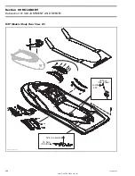
1
F18K0XA
TYPICAL — GTX MODEL SHOWN
1. Remove screw
Remove cross support plate from the inside of
bilge.
Inspection
Check for cracks and deterioration of screw
threads on cross support plate, replace if neces-
sary.
Verify the condition of gasket
no. 38
before instal-
lation, replace if necessary.
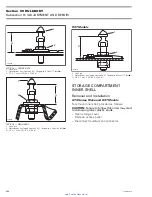
1
F18K1BA
2
1. Gasket
2. Support plate
Assembly
Assembly is the reverse process of disassembly,
make sure of the following when doing assembly:
Install the gasket on the cross support plate.
F18K1CA
GASKET INSTALLED ON SUPPORT PLATE
From inside the bilge, install the cross support
plate. Place the gasket against the hull then align
the holes.
Torque screw
no. 37
to 1.2 N•m (10 lbf•
in
).
smr2005-039
249
www.SeaDooManuals.net


