


Section 07 PROPULSION
Subsection 01 (JET PUMP)
F02J0TA
1
1
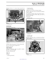
1. Torque screws to 21 N•m (16 lbf•ft)
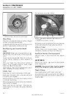
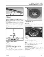
PUMP PRESSURIZATION
Whenever doing any type of repair on jet pump, a
pressure test should be done to check for leakage.
Proceed as follows:
– Remove impeller cover
no. 26
. Install the pres-
sure cap (P/N 529 035 843) on pump housing.
– Connect pump includes in the vacuum/pressure
pump kit (P/N 529 031 800) to fitting.
– Pressurize pump to a maximum of 70 kPa
(10 PSI).
529 035 843
F18J19A
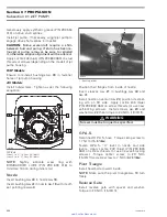
– Pump must maintain this pressure for at least 5
minutes.
CAUTION:
Repair any leak, failure to correct a
leak will lead to premature wear of pump com-
ponents.
NOTE:
If there is a pressure drop spray soapy wa-
ter around cover. If there are no bubbles, impeller
shaft, impeller shaft seal, or jet pump housing is
leaking through porosity and has to be replaced.
Jet pump unit has to be disassembled. There may
be 2 or 3 bubbles coming out from the area of
sleeve
no. 30
and its seal
no. 29
. This small leak
is acceptable. Leaks from other areas must be re-
paired.
– Disconnect pump and remove pressure cap.
– Reinstall impeller cover with 3 new self-lock-
ing screws. Push cover against pump housing
while tightening screws.
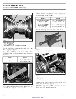
INSTALLATION
Jet Pump Housing
The water flow is controlled by a reducer located
between the jet pump support and the jet pump
on the inlet side. The reducer is color coded ac-
cording to watercraft model. See table below.
MODEL
REDUCER COLOR
GTX 4-TEC
Wake
GTX 4-TEC Limited
RXT
RXP
Yellow
GTX 4-TEC Supercharged
Red
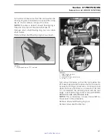
Make sure that the reducer is installed as shown.
CAUTION:
Misinstallation can cause overheat-
ing and damage to exhaust system.
1
F18J0IA
1. Color-coded reducer
smr2005-019
199
www.SeaDooManuals.net


