


Section 07 PROPULSION
Subsection 02 (DRIVE SYSTEM)
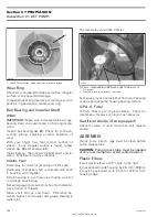
F18B02A
1
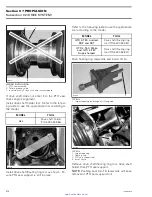
TYPICAL
1. Drive shaft holder
F18B03A
Due to configuration of some models, it may be
necessary to disconnect EGTS sensor to make
room.
Install the drive shaft/floating ring tool. Refer to
the following table to use the appropriate tool ac-
cording to the model.
MODEL
TOOL
GTX 4-TEC Limited,
RXP and RXT
Drive shaft/floating ring
tool (P/N 529 035 987)
GTX 4-TEC, Wake
and GTX 4-TEC
Supercharged
Drive shaft/floating ring
tool (P/N 529 035 841)
NOTE:
Note that there is a large opening and
a small opening on the tool. Depending on the
step involved in the procedure, it is sometimes
required to reverse its installation position.
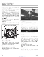
F18B04B
1
2
TYPICAL — DRIVE SHAFT/FLOATING RING TOOL
1. Small opening
2. Large opening
Install tool as shown.
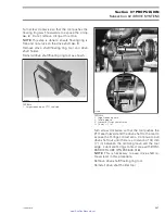
1
F18I0NA
TYPICAL
1. Largest opening on through-hull fitting side
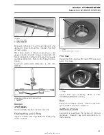
F18C02A
4
3
2
1
TYPICAL
1. Largest opening here
2. Floating ring
3. PTO seal support tool
4. Circlip
206
smr2005-020
www.SeaDooManuals.net