


Section 04 ENGINE MANAGEMENT (1503 4-TEC)
Subsection 01 (OVERVIEW)
For communication link troubleshooting, refer to
INSTRUMENTS AND ACCESSORIES in ELECTRI-
CAL section.
The communication link is also used to communi-
cate informative messages, monitoring and diag-
nostic codes to the information center and to the
VCK (vehicle communication kit) where B.U.D.S.
(Bombardier utility and diagnostic system) is used
for diagnosing and troubleshooting the system.
The fault codes can be seen from either the infor-
mation center or B.U.D.S. Refer to DIAGNOSTIC
PROCEDURES section.
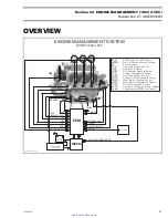
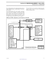
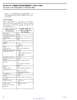
ECM and VCM Interaction with Electrical System
- COMPASS
- OUTSIDE AIR
TEMPERATURE
SENSOR
COMMUNICATION LINK
COMMUNICATION LINK
- POWER TO
ECM
- INFORMATION
CENTER
- SET AND MODE
SWITCHES
- SPEED SENSOR
- FUEL LEVEL
SENDER
- BEEPER
- DEPTH GAUGE
- START/STOP
SWITCH
- STARTING
SOLENOID
- FUEL PUMP
- FUEL INJECTORS
- IGNITION COILS
- TOPS VALVE
- TOPS SWITCH
- CAPS
INFORMATION
CENTER
ECM
MPEM
- TPS
- MAPS
- MATS
- CTS
- EGTS
- KS
- OPS
- OSPS
- CPS
- DESS
- IDLE
BYPASS
VALVE
COMMUNICATION
LINK
WH/BK
WH/RE
WH/BK
WH/RE
WH/RE
WH/BK
EMS
VCK
(communication port)
COLOR CODE
WH = WHITE
BK = BLACK
RE = RED
These components are shared between the
MPEM and the ECM. The MPEM supplies the
power while the ECM controls and completes
the circuit by switching it to the ground.
smr2005-011-002_aen
smr2005-011
71
www.SeaDooManuals.net


