


Section 07 PROPULSION
Subsection 02 (DRIVE SYSTEM)
F18B03A
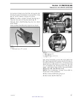
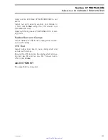
NOTE:
It will be necessary to push the shaft in to
install the drive shaft holder tool.
Reinstall drive shaft/floating ring tool as shown.
1
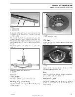
F18I0OA
TYPICAL
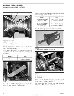
1. Largest opening on PTO seal side
Push floating ring
no. 1
rearwards to expose circlip
no. 2
and remove it.
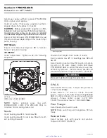
F18C02A
4
3
2
1
TYPICAL
1. Largest opening here
2. Floating ring
3. PTO seal support tool
4. Remove circlip
Remove drive shaft holder tool then drive
shaft/floating ring tool.
Place rags under PTO housing to prevent spillage.
If spillage occurs, clean immediately with the pul-
ley flange cleaner (P/N 413 711 809) to prevent oil
stains.
Remove drive shaft.
NOTE:
A slight jerk to the rear may be required to
remove the drive shaft from the PTO seal assem-
bly.
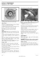
Boot
Loosen gear clamp
no. 4
holding boot
no. 5
, then
carefully pull boot and carbon ring
no. 6
from hull
insert.
Carbon Ring
Loosen gear clamp
no. 7
then pull carbon ring
no. 6
from boot
no. 5
.
INSPECTION
Drive Shaft
Inspect condition of drive shaft and PTO flywheel
splines.
Inspect condition of groove.
With your finger nail, feel machined surface of
drive shaft. If any irregular surface is found, re-
new drive shaft.
208
smr2005-020
www.SeaDooManuals.net