


Section 07 PROPULSION
Subsection 01 (JET PUMP)
Generously apply synthetic grease (P/N 293 550
010) on drive shaft splines.
Install jet pump. If necessary, wiggle jet pump to
engage drive shaft splines in impeller.
CAUTION:
Some watercraft require a shim
between hull and pump; if shim has been re-
moved at pump removal, be sure to reinstall
it, otherwise engine alignment will be altered.
Apply Loctite 243 (blue) (P/N 293 800 060) on stud
threads or screws (depending on the model) of jet
pump housing.
RXP Models
Ensure to reinstall bushings
no. 39
in fastener
holes of jet pump housing.
All Models
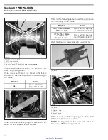
Install nuts/screws. Tighten as per the following
sequence.
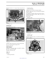
F18J1YA
3
1
5
6
2
4
TYPICAL
From 1 to 2: 16 N•m (12 lbf•ft)
From 3 to 6: 31 N•m (23 lbf•ft)
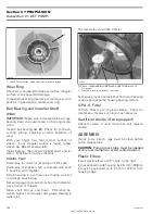
NOTE:
Slightly
lubricate
wear
ring
with
BOMBARDIER LUBE (P/N 293 600 016) to
minimize friction during initial start.
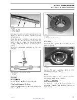
Nozzle
Insert bushing
no. 40
in nozzle
no. 18
.
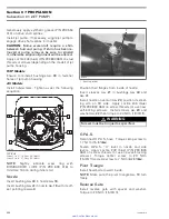
Insert bushing
no. 41
in nozzle
no. 18
with its off-
set pointing rearward.
1
F18J0GA
1. Bushing offset
Position their flanges from inside of nozzle.
Insert sleeves
no. 21
in bushings
no. 40
and
no. 41
.
Install nozzle on venturi
no. 24
; position its steer-
ing arm on RH side. Apply Loctite 243 (blue)
(P/N 293 800 060) on screw threads (or use new
self-locking screws). Install screws
no. 20
and
washer
no. 22
then torque to 24 N•m (18 lbf•ft).
WARNING
Screws must be torqued as specified.
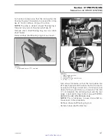
O.P.A.S.
Reconnect O.P.A.S. hose. Torque clamp screw to
1.7 N•m (15 lbf•
in
).
Fasten O.P.A.S. “U” lever to nozzle and side
levers. Apply Loctite 243 (blue) (P/N 293 800
060) on screw threads (or use new self-locking
screws).
Torque center screw to 20 N•m
(15 lbf•ft) and side screw to 7 N•m (62 lbf•
in
).
Pivot Triangle
Install head bolts toward inside.
NOTE:
Make sure the pivot triangle
no. 13
turn
freely.
Reverse Gate
Install reverse gate with spacer and washer.
Torque to 20 N•m (15 lbf•ft).
200
smr2005-019
www.SeaDooManuals.net


