


Section 04 ENGINE MANAGEMENT (1503 4-TEC)
Subsection 03 (COMPONENT INSPECTION, REPLACEMENT AND ADJUSTMENT)
1
R1503motr202A
1
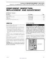
1. Locking ties
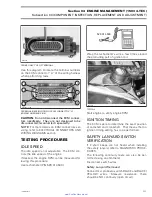
Connect the fuel injectors, ignition coils, CAPS,
CTS and EGTS to the wiring harness.
WARNING
Pay attention not to mix injectors or ignition
coils wires between cylinders. The location
of the splice connectors indicate which cylin-
der wires belong to.
Install the engine connector on the appropriate
bracket on the wiring support.
Then fix the other bundle on the appropriate sup-
ports on the wiring support and the ECM bracket
with locking ties.
1
R1503motr203A
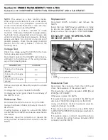
TYPICAL
1. Locking ties
Connect the CPS, KS, OPS, and the MAPS to the
wiring harness.
Also connect now the MATS, TPS, idle bypass and
TOPS valve to the wiring harness.
Fix the wiring for the MATS with a locking tie to
support the cables.
1
R1503motr204A
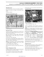
1. Locking tie
Install all remaining parts, which has been re-
moved.
FUEL INJECTOR
IMPORTANT:
Never mix up fuel injectors of
naturally-aspirated and supercharged 4-TEC en-
gines.
Doing so will automatically lead to a
misfunction of the EMS and will cause a bad
engine calibration.
Leakage Test
To perform a leakage test, the injectors and fu-
el rail have to be removed from the engine. See
FUEL INJECTOR REPLACEMENT below for the
procedure.
NOTE:
Do not detach injectors from the fuel rail.
Reconnect the fuel line and the wiring harness.
Place each injector in a clean bowl.
Install the safety lanyard cap on the DESS post to
activate the fuel pump.
Check for fuel leakage from the injector nozzle.
There should be less than 1 drop per minute. Per-
form the test for 2 minutes.
If not within specification, replace the fuel injec-
tor(s).
Properly reinstall removed parts.
smr2005-013
115
www.SeaDooManuals.net


