


Section 03 ENGINE SYSTEM
Subsection 05 (REMOVAL AND INSTALLATION)
1
F19D09A
2
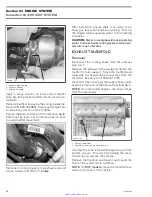
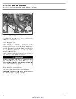
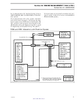
1. Lift steel rope/chain here to rotate engine
2. Usual lifting brackets
All Models
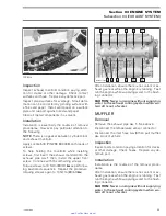
Removal of Remaining Components
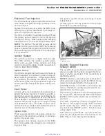
Disconnect RED positive cable from starter post.
1
F18D12A
TYPICAL
1. Disconnect RED positive cable
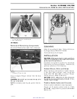
Carry on engine lifting to remove from the body
opening.
CAUTION:
Be careful not to scratch body or to
hit any component.
NOTE:
An engine stand may be used to hold en-
gine.
F00B1XA
CLEANING
Wipe off any spillage in bilge. Clean with the pul-
ley flange cleaner (P/N 413 711 809).
Clean external parts of engine.
INSTALLATION
CAUTION:
Whenever engine is removed from
watercraft, engine/jet pump alignment must be
performed at reinstallation.
Installation of engine in watercraft is essentially
the reverse of removal procedures. However pay
particular attention to the following.
Rubber Mount, Shim and Screw
Check tightness and condition of rubber mounts.
If they have been removed, apply Loctite 243
(blue) (P/N 293 800 060) on screw threads.
Torque screws to 25 N•m (18 lbf•ft).
CAUTION:
Strict adherence to this torque is
important to avoid damaging threads of alu-
minum insert in bilge.
Positive Starter Cable and Grounds
Connect starter cable before lowering engine.
Torque nut of positive starter cable to 7 N•m
(62 lbf•
in
). Apply dielectric grease (P/N 293 550
004) on nut.
smr2005-010
63
www.SeaDooManuals.net


