PAGE 48
7.3 12 & 24 INCH BRAKES
Brakes are component tools designed to bend and form mild steel. They are shipped standard with dies to
accommodate material up to 1/4 of an inch (6.3mm) thickness.
7.3A 12 & 24 INCH BRAKE INSTALLATION
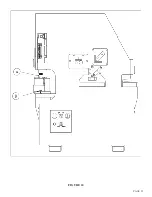
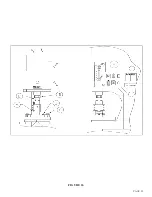
SEE FIGURE 22 ON THE FOLLOWING PAGE.
PRIOR TO INSTALLING A BRAKE ON THIS MACHINE, THE SELECTOR SWITCH MUST
BE IN THE "PUNCH" POSITION TO OPERATE THIS TOOL.
The brake is installed in the punch station and secured to the punch bed (B) with finger clamps (A).
1.
Place the selector switch in the PUNCH position and allow the ram to retract. Turn the power to
the machine off.
2.
Install the brake on the punch bed (B), using the finger clamps provided.
NOTE: THE TWELVE INCH BRAKE MOUNTS AS SHOWN IN FIGURE 22. THE TWENTY
FOUR INCH BRAKE MOUNTS 180 DEGREES FROM THE INSTALLATION SHOWN IN
FIGURE 22.
3.
After the tool is secured to the machine, make sure that the punch ram is aligned directly over the
center of the brake.
4.
Place the selector switch in the START position and the run/jog switch in the JOG position.
5.
Power the machine and place the selector switch in the PUNCH position.
6.
Jog the ram down to the brake, allowing 1/8 of an inch (3mm) between the ram and the tool. Set
the upper stroke control.
7.
Place the run/jog switch in the RUN position.
THREE VERY IMPORTANT POINTS TO REMEMBER:
1.
Never allow any part of your body to get between the upper and lower dies of a brake.
2.
Brakes must be center loaded. Never side load a brake; it will put undue pressure on the guide
parts, causing damage to the tool and an unsatisfactory bend.
3.
Never hold the workpiece while performing a bending operation.
Summary of Contents for FI-8510-20M
Page 10: ...PAGE 9 FIGURE 1...
Page 12: ...PAGE 11 FIGURE 2...
Page 24: ...PAGE 21 FIGURE 6...
Page 26: ...PAGE 23 FIGURE 7...
Page 38: ...PAGE 35 FIGURE 15...
Page 40: ...PAGE 37 FIGURE 16...
Page 42: ...PAGE 39 FIGURE 17...
Page 48: ...PAGE 45 FIGURE 20...
Page 50: ...PAGE 47 FIGURE 21...
Page 52: ...PAGE 49 FIGURE 22...
Page 56: ...PAGE 53 FIGURE 24...
Page 58: ...PAGE 55 FIGURE 25...
Page 62: ...PAGE 59 FIGURE 26...
Page 64: ...PAGE 61 FIGURE 27...
Page 68: ...PAGE 65 FIGURE 29...
Page 74: ...PAGE 71 FIGURE 30...
Page 76: ...PAGE 73 FIGURE 31...
Page 80: ...PAGE 77 FIGURE 33...
Page 82: ...PAGE 79 FIGURE 34...
Page 84: ...PAGE 81 FIGURE 35...
Page 88: ...PAGE 85 FIGURE 37...
Page 90: ...PAGE 87 FIGURE 38...
Page 92: ...PAGE 89 FIGURE 39...
Page 94: ...PAGE 91 FIGURE 40...
Page 96: ...PAGE 93 FIGURE 41...
Page 100: ...PAGE 97 FIGURE 43 SERIAL S 4481 UP...

